
Urea injection system controlled by valve group and control method thereof

A urea injection system and valve group control technology, which is applied to the electronic control of exhaust gas treatment devices, diagnostic devices of exhaust gas treatment devices, machines/engines, etc. problem, to achieve the effect of high cost, cost saving and high precision

Active Publication Date: 2021-11-23
DONGFENG COMML VEHICLE CO LTD
View PDF18 Cites 0 Cited by
  • Summary
  • Abstract
  • Description
  • Claims
  • Application Information

AI Technical Summary

Problems solved by technology

[0003] The current urea injection system has two working modes: 1) The motor urea pump pumps and measures the urea solution into the exhaust pipe. This kind of urea injection system driven by a motor will have poor measurement accuracy due to fluctuations in urea pressure. ; 2) High pressure is applied in the urea tank, and the compressed gas in the urea tank is used to pump the urea into the exhaust pipe, which cannot be purged and is easy to crystallize. In patents CN201610083835.7 and CN201610084047.X, the air pipe to the nozzle There is a purge solenoid valve on the road, which can solve the residual urea on the urea pipeline from the connection with the air pipeline to the nozzle after parking, but the residual urea on the urea pipeline from the urea tank to the connection with the air pipeline cannot be purged Therefore, there is still residual liquid in the urea pipeline

Method used


Image

  • Urea injection system controlled by valve group and control method thereof
  • Urea injection system controlled by valve group and control method thereof
  • Urea injection system controlled by valve group and control method thereof

Examples


Embodiment 1

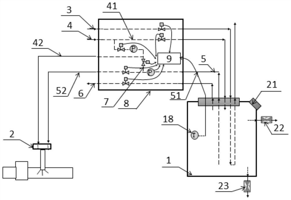
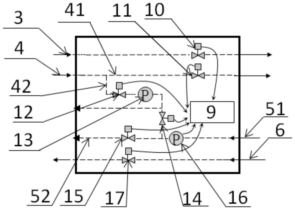
[0055] Such as Figure 1-2 As shown, a urea injection system controlled by a valve group provided by the present invention includes a urea tank 1, a urea nozzle 2, a cooling water pipeline 3, a compressed air pipeline 4, a urea pipeline 5, an air release pipeline 6, a purge pipeline 7, Valve group injection unit 8.

[0056] The connection relationship between each pipeline is: the cooling water pipeline 3 flows through the urea tank 1, and the compressed air pipeline 4 is divided into the first air pipeline 41 and the second air pipeline 41 which are connected in parallel and lead to the urea tank 1 and the urea nozzle 2 respectively after being led out from the air source. Air pipeline 42, urea pipeline 5 leads to urea nozzle 2 from urea tank 1, and deflation pipeline 6 is drawn from urea tank 1 to open atmosphere, and purge pipeline 7 is communicated with urea pipeline 5 and second air pipeline 42, and urea pipeline 5 includes Leading from the urea tank 1 to the front urea ...

Embodiment 2

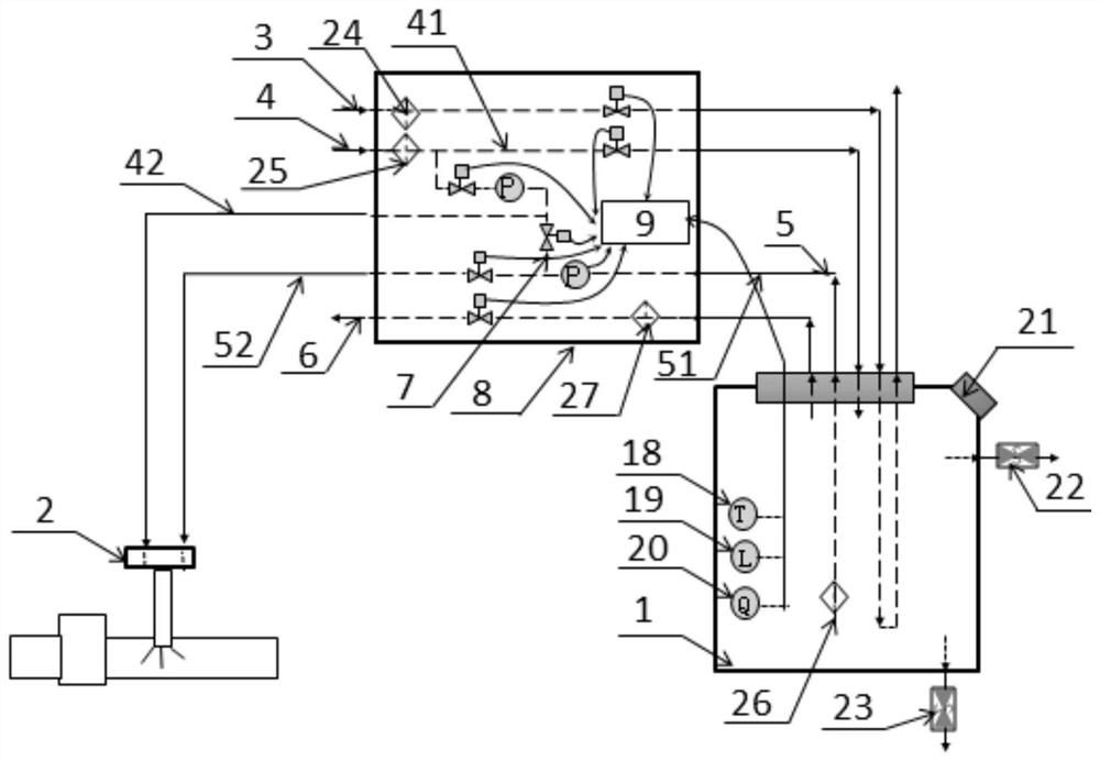
[0086] Such as image 3 As shown, the urea injection system controlled by a valve group provided in this embodiment is the same as that of Embodiment 1 except for the following structure: the urea tank 1 is also provided with a liquid level sensor 19, a concentration sensor 20, a liquid level sensor 19. The concentration sensor 20 is connected with the signal of the controller 9, the inlet of the cooling water pipeline 3 is provided with a cooling water filter 24, the inlet of the compressed air pipeline 4 is provided with an air filter 25, and the inlet of the urea pipeline 5 is provided with a urea filter 26 , The deflation pipeline 6 is provided with an atmospheric filter 27.

[0087] The control method of the urea injection system in this embodiment is the same as that in Embodiment 1, and will not be repeated here.

Embodiment 3

[0089] Such as Figure 4-5 As shown, the urea injection system controlled by a valve group provided in this embodiment has the same structure as that of Embodiment 1 except that the pressure regulating device 13 is a proportional solenoid valve.

[0090] The control method of the urea injection system in this embodiment, except for step S3, the other steps are the same as those in Embodiment 1, and will not be repeated here.

[0091] S3. Control the mixed injection of compressed air and urea

[0092] The pressure in the urea tank 1 is the target value and the controller 9 receives the urea injection command, opens the second air solenoid valve 12 and the pressure regulating device 13 to control the pressure on the second air pipeline 42, and the operation is: the second air solenoid valve 12 is fully open, adjust the proportional solenoid valve duty ratio to the required duty ratio measured under the previous normal working pressure, so that the pressure on the second air pip...


PUM


Abstract

The invention discloses a urea injection system controlled by a valve group and a control method thereof. The urea injection system comprises: a urea tank, a urea nozzle, a cooling water pipeline, a compressed air pipeline, a urea pipeline, an air release pipeline, a purging pipeline, and a valve group Injection unit; the valve group injection unit includes a controller, a cooling water solenoid valve, a first air solenoid valve, a second air solenoid valve and a pressure regulating device, a purge solenoid valve, an injection solenoid valve, a pressure sensor, and a deflation solenoid valve ,Temperature Sensor. The whole system is powered by compressed air and measured by various solenoid valves. There are also temperature sensors and pressure sensors for feedback control of the opening of the solenoid valves to complete the urea injection process with low cost and high precision; set up special purge pipes and The purge solenoid valve can purge the front and rear sections of the urea pipeline respectively, so that there is no urea residue in the whole urea pipeline after parking.

Description

technical field [0001] The invention relates to aftertreatment of exhaust gas, in particular to a urea injection system controlled by a valve group and a control method thereof. Background technique [0002] At present, Urea-SCR technology is considered to be the most effective way to reduce NOX emissions from vehicle diesel engines. After spraying urea aqueous solution with a mass fraction of 32.5% into the exhaust pipe through the urea injection system, it needs to go through collision, evaporation, hydrolysis, pyrolysis, etc. The process converts to NH3, which then reacts with NOx. [0003] The current urea injection system has two working modes: 1) The motor urea pump pumps and measures the urea solution into the exhaust pipe. This kind of urea injection system driven by a motor will have poor measurement accuracy due to fluctuations in urea pressure. ; 2) High pressure is applied in the urea tank, and the compressed gas in the urea tank is used to pump the urea into th...

Claims


Application Information

Patent Timeline
Patent Type & Authority Patents(China)
IPC IPC(8): F01N3/20F01N11/00
CPCF01N3/2006F01N3/2066F01N3/208F01N11/002F01N2570/14F01N2610/02F01N2610/14F01N2610/1426F01N2610/1453F01N2610/146F01N2610/148F01N2610/1486F01N2610/1493Y02T10/12Y02T10/40Y02A50/20
Inventor 陈旭冯坦张远徐傲陈镇何胜勇许法亮刘志辉李志明侯甲成
Owner DONGFENG COMML VEHICLE CO LTD
Learn More