
Liquid hydrogen vaporization control method for hydrogen energy unmanned aerial vehicles

A control method and technology of unmanned aerial vehicle, applied in the direction of engine control, mechanical equipment, combustion engine, etc., can solve the problems of no major advantages, storage container consumption, high thermal insulation design requirements, and achieve the goal of reducing self-weight and improving utilization efficiency. Effect

Active Publication Date: 2018-12-07
CHINA ELECTRONIC TECH GRP CORP NO 38 RES INST
View PDF6 Cites 0 Cited by
  • Summary
  • Abstract
  • Description
  • Claims
  • Application Information

AI Technical Summary

Problems solved by technology

The inner layer of the traditional hydrogen storage container is generally made of metal materials with good hydrogen resistance (such as stainless steel). Due to the high requirements for thermal insulation design, the weight of the storage container is mainly consumed in the thermal insulation design. The hydrogen storage tank can only carry 17kg of liquid hydrogen, which has no great advantage over ordinary aviation gasoline or kerosene storage
At the same time, a liquid hydrogen storage tank with good heat insulation design also has high heat insulation requirements for the hydrogen supply pipeline, which increases the weight of the pipeline. At the same time, it needs to add a special vaporizer to vaporize the liquid hydrogen, which increases the design weight.

Method used


Image

  • Liquid hydrogen vaporization control method for hydrogen energy unmanned aerial vehicles
  • Liquid hydrogen vaporization control method for hydrogen energy unmanned aerial vehicles
  • Liquid hydrogen vaporization control method for hydrogen energy unmanned aerial vehicles

Examples


Embodiment Construction

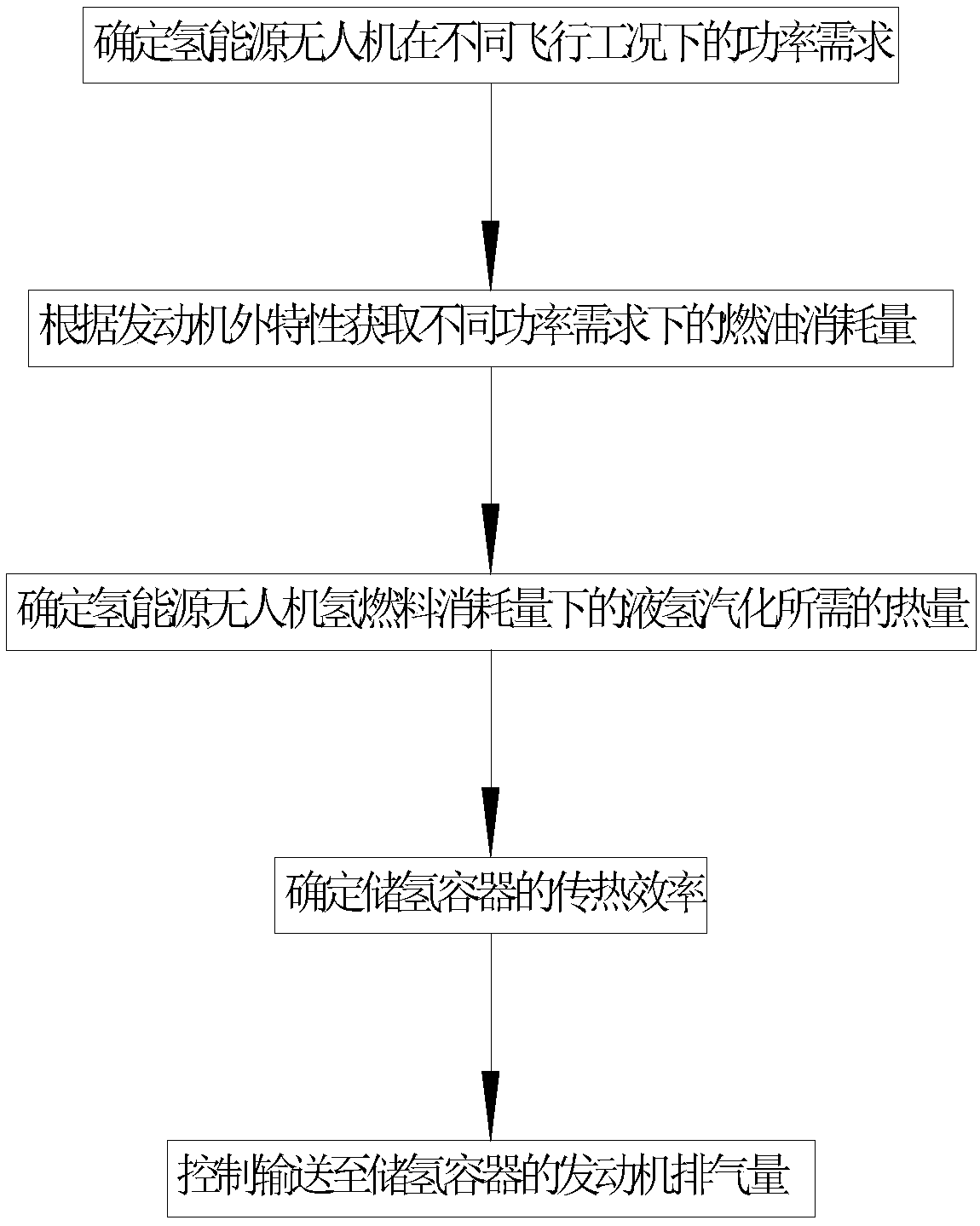
[0033] For ease of understanding, the attached figure 1 The specific implementation steps of the present invention are described as follows:

[0034] A method for fuel management of a hydrogen energy unmanned aerial vehicle based on liquid hydrogen vaporization control, comprising the following steps:

[0035] Step 1: Determine the power requirements of the hydrogen energy UAV under various flight conditions;

[0036] Step 2: Obtain the hydrogen fuel consumption under different power requirements according to the external characteristic curve of the engine;

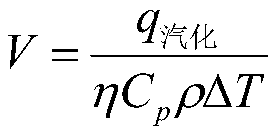
[0037] Step 3: Determine the heat required for the vaporization of liquid hydrogen under the hydrogen fuel consumption of the hydrogen energy UAV;

[0038] Step 4: Determine the heat transfer efficiency of the hydrogen storage container;

[0039] Step 5: Control the exhaust volume of the engine delivered to the hydrogen storage container to balance the vaporization amount of liquid hydrogen in the hydrogen storage cont...


PUM


Abstract

The invention relates to the technical field of fuel management of hydrogen energy unmanned aerial vehicles, and particularly relates to a liquid hydrogen vaporization control method of a hydrogen energy unmanned aerial vehicle. The design requirement of heat insulation of a hydrogen storage container is reduced, and the liquid hydrogen vaporization capacity of the hydrogen storage container is controlled in real time by virtue of exhaust waste heat of an engine, so that the liquid hydrogen vaporization capacity is balanced with hydrogen fuel consumption in all flight conditions of the unmanned aerial vehicle, thereby effectively reducing the weight of a fuel management system of the hydrogen energy unmanned aerial vehicle, increasing the payload weight of the unmanned aerial vehicle, simplifying active vaporization control and reducing the spillage of liquid hydrogen. According to the liquid hydrogen vaporization control method, the liquid hydrogen vaporization capacity is controlled by utilizing the waste heat of the engine, the engine displacement is adjusted according to the hydrogen fuel consumption, and dynamic real-time control can be performed according to different hydrogen fuel consumption, so that the utilization efficiency of hydrogen energy is improved, the self weight of the hydrogen storage container is reduced, and a reliable and feasible method is provided for the fuel management of the hydrogen energy unmanned aerial vehicle.

Description

technical field [0001] The invention relates to the technical field of fuel management of a hydrogen energy unmanned aerial vehicle, in particular to a liquid hydrogen vaporization control method for a hydrogen energy unmanned aerial vehicle. Background technique [0002] Hydrogen energy UAVs generally use fuel cells or hydrogen fuel engines as power devices, and the patent of this invention is mainly aimed at UAVs that use hydrogen fuel engines as power devices. The density of liquid hydrogen at normal temperature and pressure is 845 times that of gaseous hydrogen, and the volume energy density of liquid hydrogen is more than 10 times higher than that of gaseous hydrogen. Therefore, most of the hydrogen energy drones in the world currently use liquid hydrogen storage. . Liquid hydrogen storage requires cooling hydrogen to -253 degrees Celsius to become a liquid, and then storing it in a high-vacuum insulated container for use. Due to the large difference between the liqui...

Claims


Application Information

Patent Timeline
IPC IPC(8): F02M21/06F02D19/02
CPCF02D19/021F02M21/06Y02T10/12Y02T10/30
Inventor 赵昌霞荣海春吴晴李翔周星
Owner CHINA ELECTRONIC TECH GRP CORP NO 38 RES INST
Learn More