Buffer device for telescopic hydraulic cylinder of folding arm type truck mounted crane

A technology of telescopic hydraulic cylinder and buffer device, applied in the direction of fluid pressure actuating device, crane, etc., can solve the problems of heavy object swing, the safety of the whole machine, stability impact, and the offset of the center of gravity of hoisting heavy objects, so as to eliminate the impact. force and noise, improved smoothness, improved stability

Inactive Publication Date: 2016-11-23
湖北佳恒科技股份有限公司
View PDF0 Cites 2 Cited by
  • Summary
  • Abstract
  • Description
  • Claims
  • Application Information

AI Technical Summary

Problems solved by technology

[0003] Under the action of a telescopic hydraulic cylinder without a buffer device, when the piston rod runs to the end of the stroke, due to the sudden collision and fit between the upper end surface of the telescopic oil cylinder piston and the lower end surface of the guide sleeve, the traditional crane arm cylinder will Also emergency stop movement, the weight hoisted by the crane is under the action of inertial force, and the hoisting weight at the lower end will cause the center of gravity to shift and the weight to swing due to the emergency stop, which will greatly affect the safety and stability of the whole machine. influences

Method used


Image

  • Buffer device for telescopic hydraulic cylinder of folding arm type truck mounted crane
  • Buffer device for telescopic hydraulic cylinder of folding arm type truck mounted crane
  • Buffer device for telescopic hydraulic cylinder of folding arm type truck mounted crane

Examples


Embodiment Construction

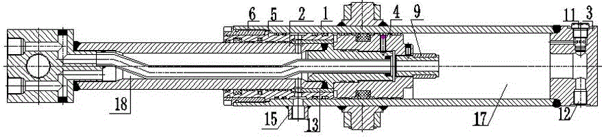
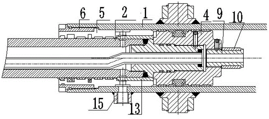
[0017] The present invention as figure 1 , 2 , 3, 4, and 5.

[0018] A telescopic hydraulic cylinder buffer device for a folding-arm type truck-mounted crane, comprising a cylinder barrel, a base 3 is provided at the tail end of the cylinder barrel 1, a piston rod 2 is installed inside the cylinder barrel 1, and a gap between the tail of the piston rod 2 and the inner wall of the cylinder barrel 1 is provided. There is a piston 4 between them, and a guide sleeve 5 is provided between the inner wall of the front cylinder 1 of the piston rod 2, and the guide sleeve 5 is fixed by the gland 6, so that the piston rod 2 slides along the inside of the guide sleeve 5, and the piston rod 2 There is a working end 7 on the top, and the cavity inside the piston rod 2 is provided with an oil pipe 8 along its length. , the tail end of the piston 4 is provided with a buffer sleeve-10 through the buffer sleeve gland 9, and the buffer sleeve-10 is co-installed with the base 3, and the base 3...


PUM


Abstract

The invention discloses a buffer device for a telescopic hydraulic cylinder of a folding arm type truck mounted crane. A cavity is formed in a piston rod and further provided with an oil pipe in the length direction of the cavity, and the two ends of the oil pipe penetrate out of a piston and a head so that a rodless cavity oil line can be formed; the tail end of the piston is provided with a first buffer sleeve through a buffer sleeve gland; a base is internally provided with a first rodless oil cavity oil inlet through a one-way valve, and the first rodless oil cavity oil inlet communicates with the rodless cavity oil line; the head is provided with a second rodless oil cavity oil inlet connected with the oil pipe and further provided with a second rod oil cavity oil inlet, and the second rod oil cavity oil inlet and the cavity in the piston rod form a rod oil cavity; the rod oil cavity communicates with the second rod oil cavity oil inlet through oil holes formed in the piston rod; and a first rod oil cavity oil inlet penetrates through a guide sleeve from the side wall of a cylinder barrel and communicates with the rod oil cavity. The two oil lines are conducive to telescopic movement of the piston rod, and the floating buffer sleeve is additionally arranged so as to limit the hydraulic oil flow, so that a decelerating buffer effect of stretching out and drawing back is achieved; and accordingly the smoothness and safety of the crane in the operation process are improved.

Description

technical field [0001] The invention relates to a hydraulic cylinder buffer device, in particular to a folding-arm type telescopic hydraulic cylinder buffer device for a truck-mounted crane. Background technique [0002] As an important part of the folding arm type truck-mounted boom, the telescopic hydraulic cylinder can not only control the extension and retraction of the boom, but also play a role in sharing and supporting the boom to lift heavy objects. The traditional (bundle type) telescopic hydraulic cylinder is limited by the installation space, and is usually designed with a slender bore (bore ≤ 100mm, stroke ≥ 1600mm). At the same time, the expansion and contraction speed and frequency are required to be "fast" to improve work efficiency. [0003] Under the action of a telescopic hydraulic cylinder without a buffer device, when the piston rod runs to the end of the stroke, due to the sudden collision and fit between the upper end surface of the telescopic oil cylin...

Claims


Application Information

Patent Timeline
IPC IPC(8): B66C23/693B66C23/88F15B15/22
Inventor 赵伟雷俊罗金盛
Owner 湖北佳恒科技股份有限公司
Why Eureka
Try Eureka