
A casing heat transfer tube

A technology of heat transfer tube and casing type, which is applied in the field of heat transfer tubes. It can solve the problems of affecting the heat transfer effect, the difficulty of liquid flowing down, and the insufficient liquid supply of the heat transfer tube, so as to achieve long-distance heat transfer and improve heat transfer efficiency. Effect

Active Publication Date: 2019-03-26
BEIJING FULLLINK OREITH TECH CO LTD
View PDF4 Cites 0 Cited by
  • Summary
  • Abstract
  • Description
  • Claims
  • Application Information

AI Technical Summary

Problems solved by technology

However, since the heat transfer tube is a single channel, evaporated steam and condensed liquid co-exist in the heat transfer tube, the liquid flows down along the outer wall, the gas rises along the outer wall, and the reverse flow produces convective resistance, making it difficult for the liquid to flow down, and the liquid is in the process of flowing down The middle part evaporates and vaporizes, resulting in insufficient liquid supply in the heat transfer tube, thus affecting the heat transfer effect

Method used


Image

  • A casing heat transfer tube

Examples


Embodiment Construction

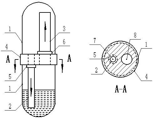
[0013] figure 1 Shown is a sleeve-type heat transfer tube, including two open heat pipes (1), a liquid catheter (2), an air pipe (3), a perforated partition (4), a connecting joint (5), The connection joint 2 (6) organically connects the above components into a whole, vacuumizes the inside of the tube and injects heat transfer working medium to form a sleeve-type heat transfer tube.

[0014] The manufacturing process of the sleeve type heat transfer tube proposed by the present invention is: two through holes are opened on the perforated partition (4), the through hole for the liquid guide tube (7) and the through hole for the air guide tube (8), and the liquid guide tube The diameter of the tube through hole (7) is smaller than the air guide tube through hole (8) to meet the requirement that the gas flow rate is greater than the liquid flow rate; connect the catheter tube (2) to the catheter tube through hole (7) through the connection joint one (5) ), connect the air guide ...


PUM


Abstract

The invention discloses a casing pipe type heat transfer pipe. The heat transfer pipe is mainly composed of two opening heat guide pipes, a liquid guide pipe, an air guide pipe, an opening partition plate, a first connecting joint and a second connecting joint; the interior of the heat transfer pipe is subject to vacuum pumping, heat transfer working media are injected to the heat transfer pipe, heat exchange can be carried out, the evaporation segment on the lower portion of the heat transfer pipe absorbs heat under the high-temperature environment so as to enable liquid-state working media in the pipe to be evaporated into gas, the gas ascends to enter the condensation segment on the upper portion of the heat transfer pipe through the air guide pipe, gas is condensed into liquid, the liquid flows downwards along the outer wall under the gravity effect, the liquid returns to the evaporation segment of the lower portion of the heat transfer pipe again through the liquid guide pipe, and heat exchange cycle can be completed. The diameter of the opening partition plate is slightly larger than the opening heat guide pipes, and therefore the heat transfer pipe is welded and sealed; the liquid guide pipe is made of a heat insulation material, the fine pipe diameter is selected, and the liquid guide pipe is connected to a liquid guide pipe through hole of the opening partition plate; the air guide pipe is made of a heat insulation material, a thick pipe diameter is selected, and the air guide pipe is connected to an air guide pipe through hole of the opening partition plate; after the first connecting joint and the second connecting joint are connected, certain mechanical strength is needed; the casing pipe type heat transfer pipe achieves air and liquid separation, the heat transfer efficiency is improved, and long-distance heat transfer is achieved.

Description

technical field [0001] The invention relates to a heat transfer tube, in particular to a casing type heat transfer tube. Background technique [0002] The function of the heat transfer tube is the transfer of heat, which is mainly composed of an evaporation section and a condensation section, and the heat transfer working fluid is injected into the tube. The evaporation section of the heat transfer tube is placed in an environment with a relatively high temperature. The high temperature environment transfers heat to the heat transfer working medium inside the heat transfer tube to evaporate the working medium, and then the heat transfer working medium steam is formed inside the heat transfer tube. The vacuum rises to the condensation section of the heat transfer tube, and the condensation releases heat to realize heat transfer, which can be applied to various heat transfer systems. However, since the heat transfer tube is a single channel, evaporated steam and condensed liq...

Claims


Application Information

Patent Timeline
Patent Type & Authority Patents(China)
IPC IPC(8): F28D15/02
CPCF28D15/02
Inventor 任宇宙祝长宇
Owner BEIJING FULLLINK OREITH TECH CO LTD
Learn More