Production and detection method of hardened bearing steel processing layer microstructure detection sample piece

A technology of microstructure and detection method, applied in the direction of material analysis using measurement of secondary emissions, measurement device, material analysis using wave/particle radiation, etc. problem, to achieve the effect of speeding up the grinding speed and improving the grinding quality

Inactive Publication Date: 2016-11-09
HARBIN UNIV OF SCI & TECH
View PDF7 Cites 4 Cited by
  • Summary
  • Abstract
  • Description
  • Claims
  • Application Information

AI Technical Summary

Problems solved by technology

However, when the grinder grinds at high speed, it will generate high temperature and residual stress in the grinding area, which will lead to a metamorphic layer in this area, which will seriously affect the observation results, and make the surface microstructure of the observation sample "distorted", causing serious damage to the observation results. illusion
The second is to use manual metallographic sandpaper to grind. The main feature of this method is that when grinding, use sandpaper with grains ranging from coarse to fine, which can obtain higher grinding accuracy. Due to the low grinding speed, no high temperature will be generated during the whole grinding process. And residual stress, so there will be no metamorphic layer, which is a great advantage compared to the grinder, but the manual grinding speed is low, labor-intensive, and reduces work efficiency
[0005] To sum up the advantages and disadvantages of the two commonly used grinding methods, it can be seen that grinding speed and grinding quality cannot be achieved at the same time.

Method used


Image

  • Production and detection method of hardened bearing steel processing layer microstructure detection sample piece
  • Production and detection method of hardened bearing steel processing layer microstructure detection sample piece
  • Production and detection method of hardened bearing steel processing layer microstructure detection sample piece

Examples


specific Embodiment approach 1

[0029] Specific implementation mode one: as figure 1 As shown, for the preparation and detection method of the microstructure detection sample of the hardened bearing steel processing layer, the method steps are as follows:

[0030] Step 1: Clamping and fixing the test sample 1; clamp and fix the test sample 1 with a special fixture (it can prevent chamfering on the edge of the test sample 1 when the test sample 1 is prepared), the test sample 1 is the ring part of hardened bearing steel;

[0031] In this embodiment, the outer ring of the deep groove ball bearing after hard turning is taken as the test sample 1, and the specifications of the test sample 1 are: the diameter of the outer circle is 43mm, the diameter of the inner circle is 38mm, and the width is 10mm.

[0032] Step 2: Rough grinding; the surface to be tested of the test sample 1 and the special fixture and the end face of the test surface on the same plane are used for rough grinding with a grinder, and then the...

specific Embodiment approach 2

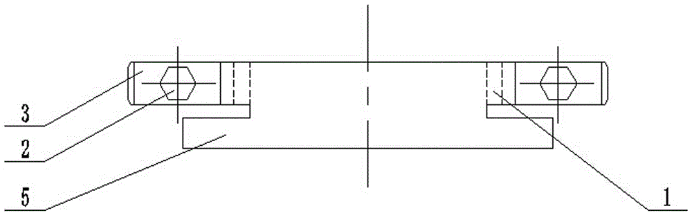
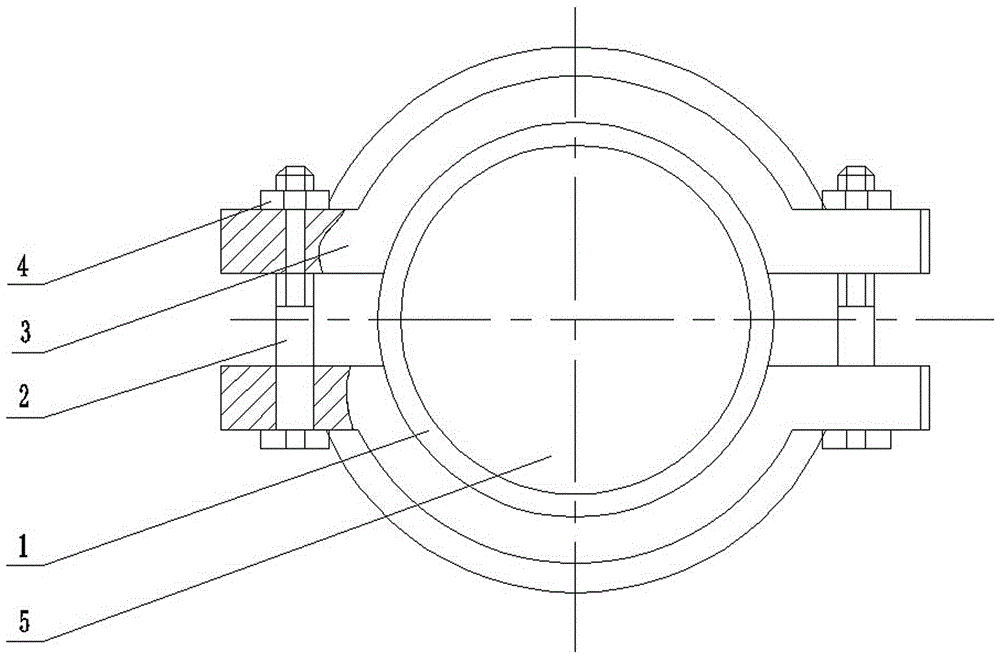
[0037] Specific implementation mode two: as Figure 2~Figure 4As shown in the specific embodiment 1, the sample preparation and detection method for the microstructure detection of the hardened bearing steel processing layer described in the first embodiment, in step 1; the special clamp includes a mandrel 5 and two semicircular clamp rings 3 , two bolts 2 and two nuts 4, each of the two ends of the semicircle-arc fixture ring 3 is provided with a fixed piece for the bolt 2 to pass through, and the two semicircle-arc fixture rings 3 are arranged opposite to form a circle Annular clamp ring, the mandrel 5 is made of coaxial and integral small-diameter cylinder and large-diameter cylinder, the small-diameter cylinder of the mandrel 5 is arranged in the circular clamp ring, The test sample 1 is set between the small-diameter cylinder of the mandrel 5 and the ring-shaped clamp ring, and the outer end surface of the test sample 1 and the ring-shaped clamp ring is located on the sam...

specific Embodiment approach 3

[0040] Specific implementation mode three: as figure 1 As shown in the specific embodiment 1, the sample preparation and detection method for the microstructure detection of the hardened bearing steel processing layer described in the first embodiment, in step 2; the surface to be detected of the detection sample 1 is roughly ground by a grinder, The grinding wheel adopts a white corundum flat grinding wheel with an abrasive grain size of 50#, the grinding speed is 380~420r / min, the feed is 0.03mm each time, and the cooling liquid is used for cooling during grinding (the grinding process can be regarded as low stress grinding , less damage to the original state of the sample surface).


PUM

PropertyMeasurementUnit
Diameteraaaaaaaaaa
Diameteraaaaaaaaaa
Widthaaaaaaaaaa

Abstract

The invention relates to a production and detection method of a hardened bearing steel processing layer microstructure detection sample piece, and belongs to the technical field of part processing and detection. The method comprises the following steps: taking a hardened bearing steel annular part, and clamping the hardened bearing steel annular part with a clamp; carrying out rough grinding flattening on the surface to be detected of the detected sample piece through using a grinder; carrying out manual fine grinding on the surface to be detected of the rough grinding qualified detected sample piece through using metallographic sand paper; mechanically polishing the fine grinding qualified detected sample piece on a polisher; coating the surface to be detected of the mechanical polishing qualified detected sample piece with an eroding liquid to carry out erosion; and preheating the surface to be detected of the eroded detected sample piece, observing the surface to be detected by using an SEM (scanning electron microscope), and measuring the microstructure of the surface to be detected of the detected sample piece and shooting the photograph of the microstructure of the surface under the SEM. The method has the advantages of maximization of the grinding efficiency and the grinding quality, realization of high definition of the surface microstructure detection of the produced sample piece, and obtaining of a real result of the observed surface microstructure.

Description

technical field [0001] The invention relates to a sample preparation and detection method for detecting the microstructure of a hardened bearing steel processing layer, and belongs to the technical field of parts processing and detection. Background technique [0002] technology [0003] With the rapid development of hard cutting technology, the evaluation of the service performance of machined parts is getting higher and higher, and the detection of the microstructure characteristics of the machined surface is the most basic evaluation standard. The study of its microstructure and formation mechanism plays an important role in ensuring the quality of the machined surface of the part. Through the research and analysis of the microstructure of the machined surface, the cutting conditions and cutting technology can be optimized or changed to improve the quality of the machined surface of the part, so as to achieve The purpose of improving the service performance of parts. Th...

Claims


Application Information

Patent Timeline
IPC IPC(8): G01N23/22
CPCG01N23/22G01N23/2202G01N23/2204
Inventor 陈涛邱长政刘献礼李素燕
Owner HARBIN UNIV OF SCI & TECH
Why Eureka
Try Eureka