
Steel pipe plastic coating hot air furnace

A technology of hot blast stove and hot air, which is applied in the direction of coating, liquid coating device on the surface, surface pretreatment, etc., which can solve the problems of dirt on the surface of the steel pipe, uneven temperature, waste of energy, etc., and achieve temperature reduction and temperature rise Fast speed and the effect of improving the working environment

Inactive Publication Date: 2016-11-09
高密天一机械科技有限公司
View PDF5 Cites 2 Cited by
  • Summary
  • Abstract
  • Description
  • Claims
  • Application Information

AI Technical Summary

Problems solved by technology

Although this kind of heating furnace can heat the steel pipe to a predetermined temperature, it is easy to cause uneven temperature on the steel pipe due to the heating of the steel pipe after the fuel is burned. Even if the heat conduction speed of the steel pipe is fast, the steel pipe must be heated to a temperature higher than that When the temperature drops to the plastic coating temperature, it is possible to form a uniform temperature. Therefore, this heating method wastes energy, and at the same time, it will also generate dirt on the surface of the steel pipe.
The most important problem is that after using this kind of heating furnace to heat the steel pipe, the furnace door must be opened and the steel pipe must be taken out. Because the operation of taking out from the high-temperature furnace and putting in the steel pipe is relatively difficult, even if it is operated by mechanical equipment, it will take more time. A long time will cause a large loss of heat in the furnace

Method used


Image

  • Steel pipe plastic coating hot air furnace
  • Steel pipe plastic coating hot air furnace
  • Steel pipe plastic coating hot air furnace

Examples


Embodiment Construction

[0031] The present invention will be further described below in conjunction with the accompanying drawings and embodiments.

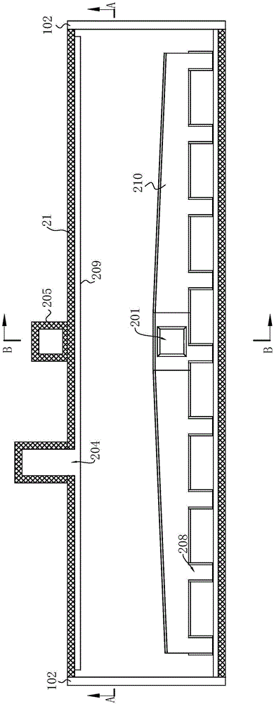
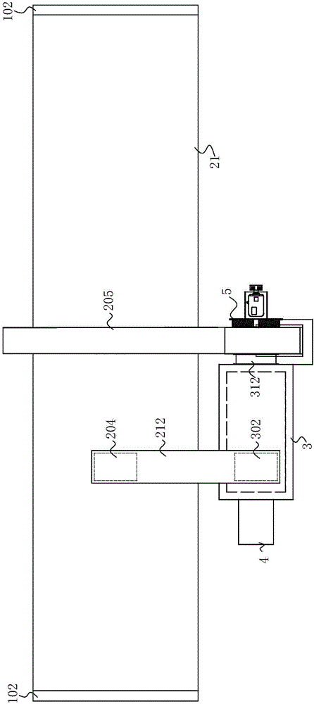
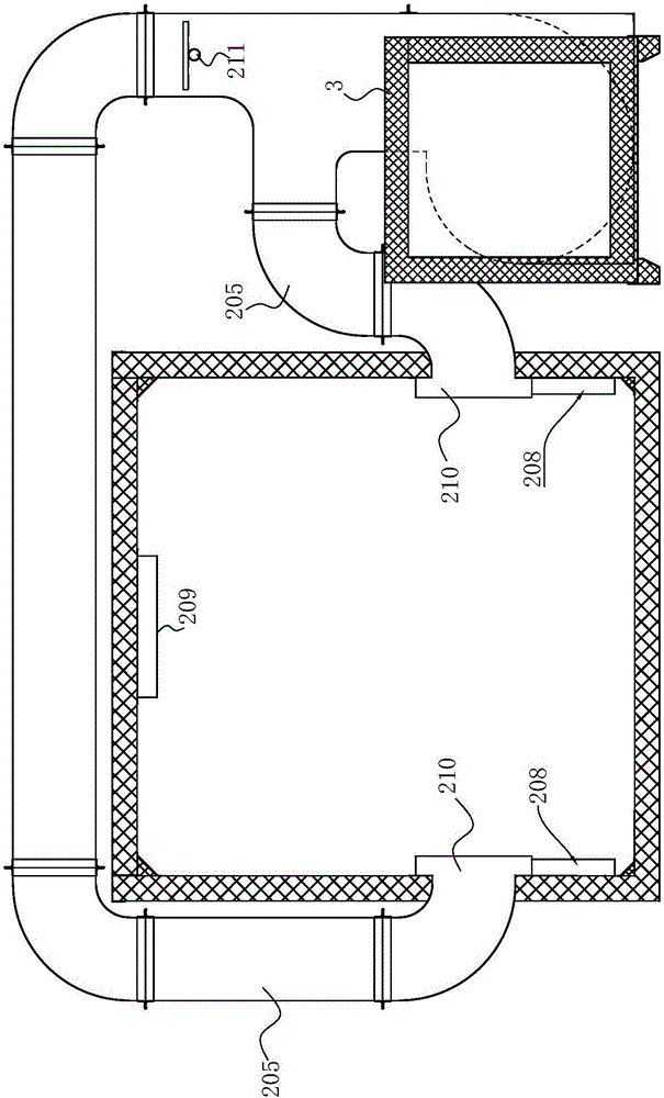
[0032] like Figure 1 to Figure 3 Commonly shown, a steel pipe plastic-coated hot air furnace includes a hot air drying tunnel 21 and a combustion chamber, and the combustion chamber is located outside the hot air drying tunnel 21 .

[0033] combine Image 6 As shown, the hot blast stove combustion chamber includes a housing 3, the housing 3 includes a first end 31 and a second end 32 oppositely arranged, and a side 33 is between the first end 31 and the second end 32, and the second One end 31 is provided with a flame injection port 311 for installing the burner 4 , and the second end 32 is provided with an air outlet 312 from which hot air is discharged, and the air outlet 312 is connected to the fan 5 . The side portion 33 of the casing 3 is provided with an air return port 302 through which the combustion chamber can recycle hot air, thereby reali...


PUM


Abstract

The invention discloses a steel pipe plastic coating hot air furnace, which comprises a hot air drying passage and a combustion chamber, wherein the combustion chamber is positioned outside the hot air drying passage; the combustion chamber is connected with a burner; the two end parts of the hot air drying passage are respectively provided with furnace doors; the top of the hot air drying passage is provided with an air return opening; air supply openings are respectively formed in the two sides of the hot air drying passage; the inner side wall of the hot air drying passage is provided with a side air passage communicating with the air supply opening of the hot air drying passage; the side air passage is provided with a plurality of hot air outlets; the combustion chamber is provided with an air outlet and an air return opening; the air outlet of the combustion chamber is connected with a fan and communicates with the air supply opening of the hot air drying passage; the air return opening of the hot air drying passage communicates with the air return opening of the combustion chamber through an air return pipeline. The hot air furnace has the advantages that the temperature rise speed is high; the hot air in the hot air drying passage is uniform; the heat efficiency is high.

Description

technical field [0001] The invention relates to the technical field of steel pipe coating equipment, in particular to a steel pipe plastic coating hot blast furnace. Background technique [0002] Plastic-coated steel pipe inside and outside, plastic-coated steel pipe inside and outside is a layer of polyethylene (PE) resin, ethylene-acrylic acid copolymer (EAA), epoxy (EP) powder, non-toxic polypropylene (PP) or non-toxic Steel-plastic composite pipes made of polyvinyl chloride (PVC) and other organic substances. Plastic-coated steel pipe not only has the advantages of high strength, easy connection, and water impact resistance, but also overcomes the shortcomings of steel pipes such as easy corrosion, pollution, scaling, low strength of plastic pipes, and poor fire performance. [0003] Large-diameter steel pipes generally refer to steel pipes with a nozzle diameter of 300mm to 2400mm, which can be coated with plastic coatings with different properties such as polyvinyl ch...

Claims


Application Information

Patent Timeline
Patent Type & Authority Applications(China)
IPC IPC(8): B05D3/02
CPCB05D3/0236
Inventor 罗峰何相友邓志昌罗旭成
Owner 高密天一机械科技有限公司
Learn More