Network voltage interruption detection and control method for multi-unit train network side converter

A grid-side converter and control method technology, which is applied in the direction of instruments, measuring electricity, measuring devices, etc., can solve the problems of power supply interruption, intensified pantograph vibration, overcurrent on the AC side of grid-side converters, etc. Normal and safe operation and the effect of reducing potential safety hazards

Active Publication Date: 2016-10-12
BEIJING JIAOTONG UNIV +1
View PDF10 Cites 4 Cited by
  • Summary
  • Abstract
  • Description
  • Claims
  • Application Information

AI Technical Summary

Problems solved by technology

However, for high-speed EMUs, the excessively high speed will cause the pantograph to vibrate intensified, and pantograph-network separation will inevitably occur
When the pantograph-catenary is separated, the high voltage between the pantograph-catenary will break down the air gap and generate an arc. As the air gap increases, when the breakdown voltage is greater than the supply voltage, the arc is extinguished, and there is a high resistance between the pantograph and the catenary. state, causing power interruption
If the grid-side converter cannot detect the power supply interruption, or does not perform any processing on the control, when the power supply is restored, it is likely to cause overcurrent on the AC side of the grid-side converter, causing false protection

Method used


Image

  • Network voltage interruption detection and control method for multi-unit train network side converter
  • Network voltage interruption detection and control method for multi-unit train network side converter
  • Network voltage interruption detection and control method for multi-unit train network side converter

Examples


Embodiment Construction

[0024] The present invention will be further described below in conjunction with the accompanying drawings and embodiments.

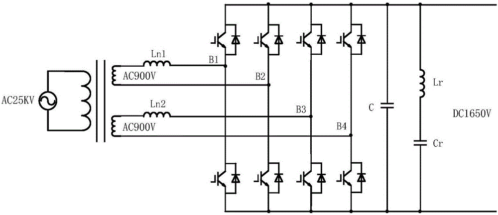
[0025] figure 1 It is a schematic diagram of the main circuit of an EMU network side converter provided by the present invention. The grid-side converter includes two parallel single-phase PWM rectifiers, the AC side of the PWM rectifier is directly connected to the two secondary windings of the traction transformer, and the DC side is connected in parallel. The main circuit of the PWM rectifier includes AC filter inductor L, power devices B1~B4, DC support capacitor C, and second harmonic filter inductor L r and the filter capacitor C r . Among them, the AC filter inductor L can greatly reduce the harmonic current injected into the AC grid by the PWM rectifier; the power devices B1~B4 use half-bridge IGBT intelligent power modules, which integrate the functions of driving, protection and current measurement, and can simplify the system. structure t...


PUM


Abstract

The invention relates to a network voltage interruption detection and control method for a multi-unit train network side converter. According to the method of the invention, a network voltage interruption detection condition is that a d-axis component Ed and a q-axis component Eq under a synchronous rotation coordinate system can be obtained after network voltage En is subjected to coordinate transformation, when the values of the d-axis component Ed and the q-axis component Eq are smaller than a certain set value X simultaneously, interruption occurs; and the amplitude and phase of bridge arm voltage Us* combined in a network voltage interruption period are controlled through a control method so to be consistent with the amplitude and phase of the network voltage En, and therefore, the network side converter can operate normally, and a fault will not be brought about. With detection means and control strategies of the multi-unit train network side converter for the network voltage interruption of a traction network adopted, the voltage interruption of the traction network can be detected fast; the network side converter can make correct control response; the normal and safe operation of equipment can be ensured; and potential safety hazards caused by bad power supply conditions of railways can be decreased.

Description

technical field [0001] The invention relates to a detection and control method for interruption of network voltage, in particular to a detection and control method for the interruption of network voltage of traction network, which is suitable for a converter on the network side of an EMU on a railway. Background technique [0002] For the traction power supply system of the electrified railway, the train mainly obtains power through the sliding contact between the pantograph on the top and the catenary. The catenary is not only an important part of the train traction power supply system, but also a relatively weak power supply device. The contact state between the pantograph and the catenary will directly affect the power quality of the train, and then affect the running state of the train. [0003] For electric locomotives running at low speed, because the contact between pantograph and catenary is relatively stable, general trains can obtain stable current. However, for h...

Claims


Application Information

Patent Timeline
IPC IPC(8): G01R31/04H02H7/28
CPCG01R31/66H02H7/28
Inventor 刁利军张钢张馨予刘志刚王磊陈杰
Owner BEIJING JIAOTONG UNIV
Why Eureka
Try Eureka