
High-precision measurement method for magnetic field compensation inertial angular rate based on of SERF (spin-exchange relaxation free) atomic device

A measurement method and angular rate technology, applied in the field of high-precision inertial-geomagnetic integrated navigation, can solve the problems of high capital consumption, large space occupation, and unreported

Active Publication Date: 2016-10-12
BEIHANG UNIV
View PDF5 Cites 32 Cited by
  • Summary
  • Abstract
  • Description
  • Claims
  • Application Information

AI Technical Summary

Problems solved by technology

[0003] The inertial measurement device and the magnetic field measurement device based on the SERF atomic spin effect have ultra-high expected sensitivity. Many research institutions at home and abroad have carried out experimental research work, but the measurement technology integrating the two has not been reported, so when the need When measuring the magnetic field and the inertial quantity at the same time, the magnetic field measurement and the inertial angular velocity measurement are often carried out under two experimental conditions and two sets of experimental equipment, which takes up a lot of space and costs a lot of money

Method used


Image

  • High-precision measurement method for magnetic field compensation inertial angular rate based on of SERF (spin-exchange relaxation free) atomic device
  • High-precision measurement method for magnetic field compensation inertial angular rate based on of SERF (spin-exchange relaxation free) atomic device
  • High-precision measurement method for magnetic field compensation inertial angular rate based on of SERF (spin-exchange relaxation free) atomic device

Examples


Embodiment Construction

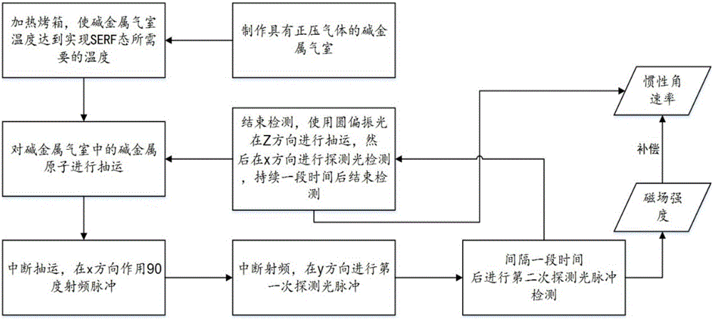
[0019] Such as figure 1 Shown, the specific implementation steps of the present invention are as follows:

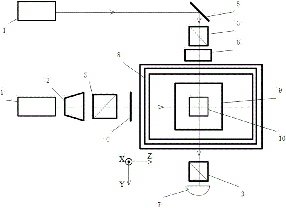
[0020] 1. Make a glass air chamber and a vacuum chamber containing alkali metals filled with positive pressure gas and vacuum conditions, and place them in such a figure 2 shown in the oven 9, figure 2 The instruments and equipment in it are: 1. DFB (distributed feedback) laser, 2. beam expander, 3. polarizer, 4. 1 / 4 wave plate, 5. plane mirror, 6. Faraday modulator, 7. Photoelectric detector, 8. Magnetic shielding barrel, 9. Non-magnetic constant temperature oven, 10. Alkali metal gas chamber.

[0021] 2. Heating the oven to make the temperature of the alkali metal gas chamber reach the temperature required for realizing the SERF state.

[0022] 3. Turn on the pumping laser to pump the alkali metal vapor in the alkali metal gas chamber for 14-15ms.

[0023] 4. Interrupt the pumping, apply a 90° radio frequency pulse perpendicular to the pumping direction (X direct...


PUM


Abstract

The invention provides a high-precision inertial angular rate measurement method based on magnetic field compensation of an SERF (spin-exchange relaxation free) atomic device. The method comprises the steps that a glass gas chamber and a vacuum gas chamber which is filled with positive pressure gas and contains alkali metal are manufactured firstly, an oven is heated to make the temperature in the alkali metal gas chamber reach a temperature required by an SERF state; an operation period begins: pumping is conducted on the alkali metal gas chamber; pumping is interrupted, and 90-degree radio-frequency pulses act in the vertical pumping direction; radio frequency is interrupted, two times of probe light pulse detection are performed in the vertical pumping direction at an interval, and the magnetic field strength can be obtained according to the above measure experimental data; then, pumping is performed for a period of time by using circularly polarized light, then probe light detection is performed in the vertical pumping direction, the experimental data and measured magnetic field strength are compensated so that the high-precision inertial angular rate can be obtained, and pumping and detection are completed. The magnetic field measurement and inertial measurement are performed in the same experimental device under the same conditions, the measured magnetic field is utilized to compensate inertial angular rate errors caused by magnetic field interferences, and the measurement accuracy is improved.

Description

technical field [0001] The invention relates to a high-precision measurement method of magnetic field compensation inertial angular rate based on SERF (Spin-Exchange-Relaxation-Free, no spin exchange relaxation) atomic device, especially a method under the same experimental conditions and the same set of experimental equipment The design of SERF atomic device for time-sharing measurement of magnetic field and inertial angular velocity can be used for high-precision inertial-geomagnetic integrated navigation. Background technique [0002] National defense and military require high-precision inertial navigation and guidance systems and extremely weak magnetic field measurement technology. At present, the difficulty of improving the accuracy of gyroscope has become the key to restrict the performance improvement of inertial navigation system. The existing high-precision gyroscopes mainly include rotor gyroscopes and optical gyroscopes, but they have encountered technical bottl...

Claims


Application Information

Patent Timeline
IPC IPC(8): G01C19/58G01R33/032G01C21/16G01C21/08
CPCG01C19/58G01C21/08G01C21/165G01R33/0322
Inventor 全伟房子善房建成李茹杰范文峰姜丽伟刘峰
Owner BEIHANG UNIV
Learn More