
Envelope tracked Doherty power amplifier

A technology of envelope amplifiers and power amplifiers, applied in power amplifiers, amplifiers, improved amplifiers to improve efficiency, etc., can solve the problems that the power value of the main power amplifier does not reach the saturation value, limit the linearity of Doherty power amplifiers, etc., to achieve increased gain, Efficiency improvement, effect of increasing gain

Inactive Publication Date: 2016-09-07
BEIJING UNIV OF POSTS & TELECOMM
View PDF3 Cites 18 Cited by
  • Summary
  • Abstract
  • Description
  • Claims
  • Application Information

AI Technical Summary

Problems solved by technology

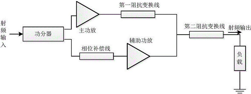
[0004] The leakage voltage value of the main power amplifier is a fixed value set according to the saturated output power of the power amplifier to ensure that the main power amplifier has the highest efficiency when outputting saturated power, but within the range of power fallback, the output power value of the main power amplifier does not The saturation value is reached, and the DC power consumption is consistent with the saturation output due to the fixed leakage voltage value, which limits the efficiency improvement of the main power amplifier within the power fallback range
The grid voltage value of the auxiliary power amplifier is a fixed value set according to the power fallback range designed by the Doherty power amplifier, so as to ensure that the auxiliary power amplifier only amplifies the signal when the input RF signal power exceeds a certain minimum threshold value, so that the auxiliary power amplifier It works in a state similar to class C, so that the efficiency of the auxiliary power amplifier is very high, but the introduction of the class C power amplifier brings serious nonlinear characteristics, and the gain compression of the auxiliary power amplifier working in the class C is much greater than that of the power class AB amplifier, limiting the optimization of the linearity of the Doherty power amplifier

Method used


Image

  • Envelope tracked Doherty power amplifier
  • Envelope tracked Doherty power amplifier
  • Envelope tracked Doherty power amplifier

Examples


Embodiment Construction

[0024] The present invention will be further described in detail below with reference to the drawings and embodiments. It should be understood that these descriptions are only exemplary and not intended to limit the scope of the present invention. In addition, in the following description, descriptions of well-known structures and technologies are omitted to avoid unnecessarily obscuring the concept of the present invention.

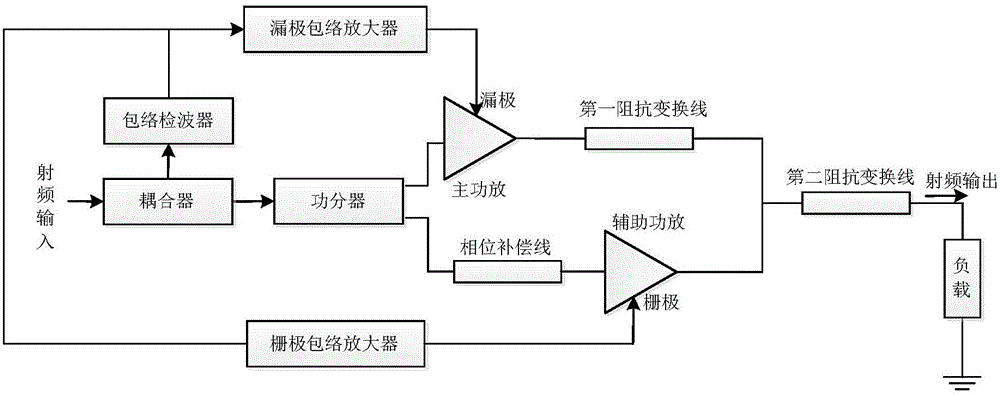
[0025] The present invention is a Doherty power amplifier with envelope tracking, such as figure 2 As shown, it includes a power divider, a main power amplifier, an auxiliary power amplifier, a first impedance transformation line, a second impedance transformation line, a phase compensation line, a coupler, an envelope detector, a drain envelope amplifier, and a gate envelope amplifier.

[0026] The RF signal input terminal is connected to the input terminal of the power splitter and the input terminal of the envelope detector through the coupler. The output...


PUM


Abstract

The invention discloses an envelope tracked Doherty power amplifier. Particularly, a radio-frequency signal input end is respectively connected with the input end of a power distributor and the input end of an envelope detector through a coupler; the output end of the power distributor is respectively connected with the input end of a main power amplifier and a phase compensation line; the phase compensation line is connected between the output end of the power distributor and the input end of an auxiliary power amplifier; the output end of the main power amplifier and the output end of the auxiliary power amplifier are coupled to a second impedance conversion line through a first impedance conversion line, and then connected to a load; the other end of the load is grounded; the output end of the envelope detector is respectively connected with the input end of a drain envelope amplifier and the input end of a grid envelope amplifier; the output end of the drain envelope amplifier is connected to the drain end of the main power amplifier; and the output end of the grid envelope amplifier is connected to the grid end of the auxiliary power amplifier. The envelope tracked Doherty power amplifier disclosed by the invention is capable of effectively amplifying a non-constant envelope modulation signal having a high peak-to-average ratio, and can be used for modern wireless communication terminal equipment or base station equipment.

Description

Technical field [0001] The invention relates to an envelope tracking Doherty power amplifier, which belongs to the design field of power amplifiers in a mobile communication system. Background technique [0002] In the past ten years or so, the design of RF power amplifiers has developed rapidly under the impetus of strict index requirements (such as efficiency, linearity, etc.). Especially after the arrival of 4G-LTE and the budding of next-generation 5G communications, the communication system has stricter requirements on the linearity of the power amplifier. In addition to linearity, high efficiency has always been a hot spot in the design of power amplifiers. With the development of 4G communications, more and more complex signal modulation methods have been proposed to fill the surge in demand for data and voice services. The evolution of the signal from a constant envelope to a peak-to-average ratio non-constant envelope, the average power of the power amplifier must be i...

Claims


Application Information

Patent Timeline
Patent Type & Authority Applications(China)
IPC IPC(8): H03F1/02H03F1/32H03F3/21
CPCH03F1/0288H03F1/32H03F3/21
Inventor 于翠屏余弦刘元安黎淑兰苏明王卫民吴永乐
Owner BEIJING UNIV OF POSTS & TELECOMM
Learn More