
Induction brazing method for edge scraper of shielding tunneling machine

A technology of induction brazing and shield machine, which is applied in the direction of welding equipment, electric heating devices, auxiliary devices, etc., can solve the problems of wear resistance and fatigue resistance decline, short welding time, steel hardness reduction, etc., to increase the service life and wear resistance, low weld residual stress, and improved shear strength

Active Publication Date: 2016-09-07
SICHUAN GUANGZHENG TECH
View PDF6 Cites 10 Cited by
  • Summary
  • Abstract
  • Description
  • Claims
  • Application Information

AI Technical Summary

Problems solved by technology

Due to the long welding time in the furnace, the brazing material is seriously lost, and the brazing effect is not good; special fixtures are required to fix the alloy position, and the process is complicated; resulting in a decrease in the hardness of the steel, and a decrease in wear resistance and fatigue resistance
Induction brazing has short welding time and high efficiency, and gradually replaces brazing in the furnace; however, due to the large size and irregular shape of the scraper of the shield machine, there are two existing brazing methods: one is to use an open heating coil from one side Start brazing, the efficiency is reduced, the labor cost is high, and the working environment is bad; the other is brazing with multi-turn square coils, but the temperature of the alloy at the center of the side scraper is quite different from that at the periphery. In order to achieve the welding effect, separate measures must be taken. One-step brazing or pre-setting solders with different melting points to solve the problem, the process is complicated

Method used


Image

  • Induction brazing method for edge scraper of shielding tunneling machine
  • Induction brazing method for edge scraper of shielding tunneling machine

Examples


Embodiment 1

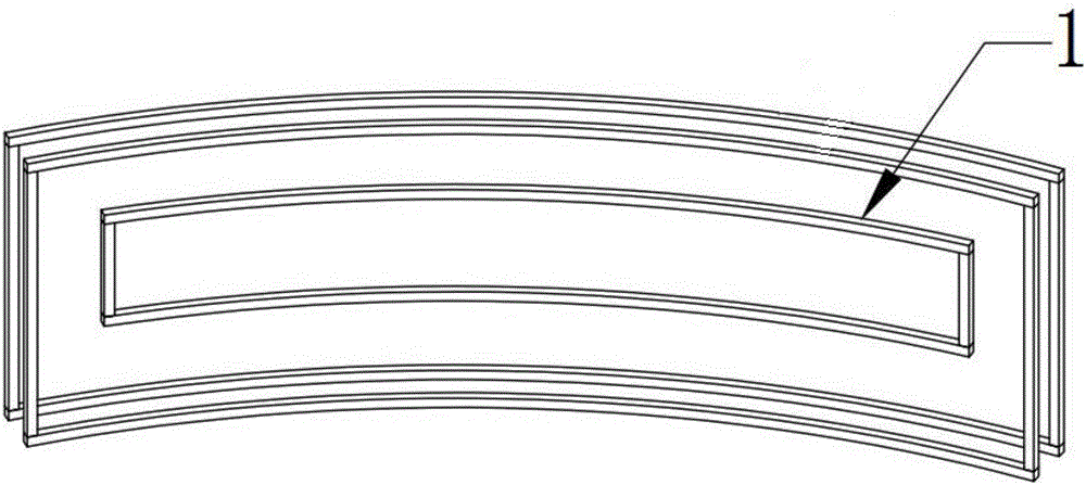
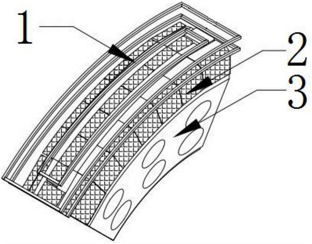
[0029] Such as figure 1 , figure 2 A shield machine edge scraper induction brazing method shown comprises the following steps:

[0030] a. Forge steel parts into arc-shaped cutter body blanks, and perform quenching and tempering treatment, and machine them into such as figure 2 Side scraper blade body 3 is shown. The cemented carbide cutter head 2 matching the side scraper is prepared by powder metallurgy, the silver-based solder is cut into a shape matching the cemented carbide cutter head 2, and then the side scraper body 3 and the cemented carbide cutter head 1 are After being assembled with silver-based solder, how to assemble is a prior art, and will not be described in detail in this embodiment.

[0031] b. Place the assembled side scraper body 3, silver-based solder, and hard alloy cutter head 2 under the profiling coil 1, adjust the position, and set the temperature measurement point of the external temperature controller to be positioned in the middle of the side...

Embodiment 2

[0042] Such as figure 1 , figure 2 A shield machine edge scraper induction brazing method shown comprises the following steps:

[0043] a. Forge steel parts into arc-shaped cutter body blanks, and perform quenching and tempering treatment, and machine them into such as figure 2 Side scraper blade body 3 is shown. The cemented carbide cutter head 2 matching the side scraper is prepared by powder metallurgy, the silver-based solder is cut into a shape matching the cemented carbide cutter head 2, and then the side scraper body 3 and the cemented carbide cutter head 1 are After being assembled with silver-based solder, how to assemble is a prior art, and will not be described in detail in this embodiment.

[0044] b. Place the assembled side scraper body 3, silver-based solder, and hard alloy cutter head 2 under the profiling coil 1, adjust the position, and set the temperature measurement point of the external temperature controller to be positioned in the middle of the side...

Embodiment 3

[0055] Such as figure 1 , figure 2 A shield machine edge scraper induction brazing method shown comprises the following steps:

[0056] a. Forge steel parts into arc-shaped cutter body blanks, and perform quenching and tempering treatment, and machine them into such as figure 2 Side scraper blade body 3 is shown. The cemented carbide cutter head 2 matching the side scraper is prepared by powder metallurgy, the silver-based solder is cut into a shape matching the cemented carbide cutter head 2, and then the side scraper body 3 and the cemented carbide cutter head 1 are After being assembled with silver-based solder, how to assemble is a prior art, and will not be described in detail in this embodiment.

[0057] b. Place the assembled side scraper body 3, silver-based solder, and hard alloy cutter head 2 under the profiling coil 1, adjust the position, and set the temperature measurement point of the external temperature controller to be positioned in the middle of the side...


PUM

PropertyMeasurementUnit
angleaaaaaaaaaa
angleaaaaaaaaaa
shear strengthaaaaaaaaaa

Abstract

The invention discloses an induction brazing method for an edge scraper of a shielding tunneling machine. An edge scraper body, silver-based brazing filler metal and a hard alloy tool bit which are well assembled are put in the lower end of a profiling coil and are tightly attached to the profiling coil, and then the welding work is completed after preheating, heating welding and post-welding thermal treatment. The adopted profiling coil is a self-made profiling coil. By means of the induction brazing method, the hard alloy at the middle part can be heated, the temperature differences of different positions of the edge scraper are reduced during welding, the same brazing filler metal can be conveniently used for brazing, and the phenomenon that because different types of brazing filler metal are used for brazing, mutual interference is caused is avoided. By means of the induction brazing method, brazing of the hard alloy tool bit and the edge scraper body can be completed at a time; and meanwhile, the weld joint brazed rate is increased, the shear strength is also improved, the service life of the edge scraper of the shield tunneling machine is prolonged, and wear resistance of the edge scraper of the shield tunneling machine is improved.

Description

technical field [0001] The invention belongs to the field of welding of dissimilar materials, in particular to an induction brazing method of a side scraper of a shield machine. Background technique [0002] The shield machine is a special construction machine for tunneling. It has the functions of excavating and cutting soil, conveying soil, assembling tunnel lining, measuring and guiding deviation correction, etc. It is mainly used in urban subway construction units, railway road tunnels and drinking water projects. The side scraper of the shield machine is a profiling tool of the cutter head of the shield machine. It is installed on the spoke base of the cutter head of the shield machine and rotates with the cutter head together with other shield tools to complete tunnel excavation and tunneling. Wait. The edge scraper used now is mainly formed by welding the cutter body and hard alloy. [0003] The blade body of the edge scraper presents a 45° arc shape, and the weldin...

Claims


Application Information

Patent Timeline
Patent Type & Authority Applications(China)
IPC IPC(8): B23K1/00B23K3/047B23K3/08
CPCB23K1/00B23K3/0478B23K3/087
Inventor 胡登文陈辉周磊江超刘艳朱忠尹
Owner SICHUAN GUANGZHENG TECH
Learn More