
A Fluid Management System for Space Fuel Tank Based on Electric Field Effect

A technology of electric field effect and fluid management, which is applied in the field of fuel storage tank fluid management system, can solve problems such as the inability to predict the specific distribution, and achieve the effect of improving the management level of on-orbit service fluid, preventing spacecraft instability, and improving active control capabilities

Active Publication Date: 2018-04-10
CHINA ACADEMY OF SPACE TECHNOLOGY
View PDF6 Cites 0 Cited by
  • Summary
  • Abstract
  • Description
  • Claims
  • Application Information

AI Technical Summary

Problems solved by technology

[0003] The effective management of fluids under microgravity conditions is a complex process. Although domestic and foreign aerospace powers have accumulated rich experience in the design of spacecraft filling tanks and fluid management during normal operation, due to the special environment of microgravity, The filling process of propellant fuel is still very different from that on the ground
In the microgravity environment of space, the gas-liquid phase of the liquid in the storage tank will not be naturally stratified due to the difference in density between the two phases, but under the action of secondary forces such as surface tension, the gas-liquid will be suspended in the storage tank together in an unsteady state. regular distribution, so its exact distribution cannot be predicted

Method used


Image

  • A Fluid Management System for Space Fuel Tank Based on Electric Field Effect
  • A Fluid Management System for Space Fuel Tank Based on Electric Field Effect
  • A Fluid Management System for Space Fuel Tank Based on Electric Field Effect

Examples


Embodiment Construction

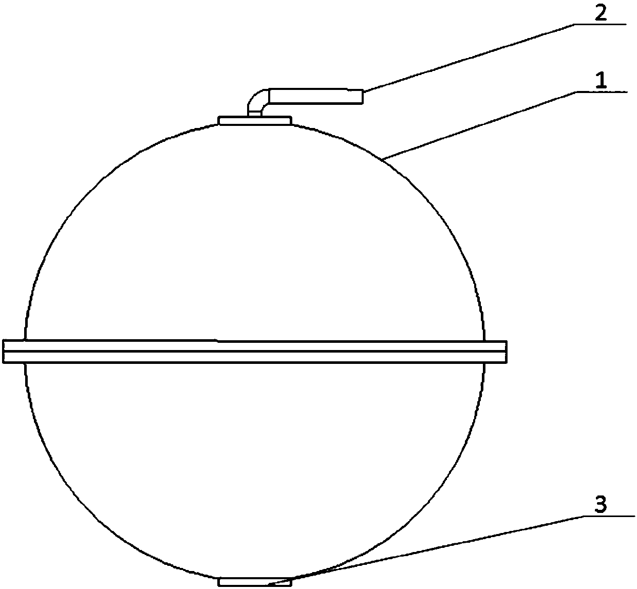
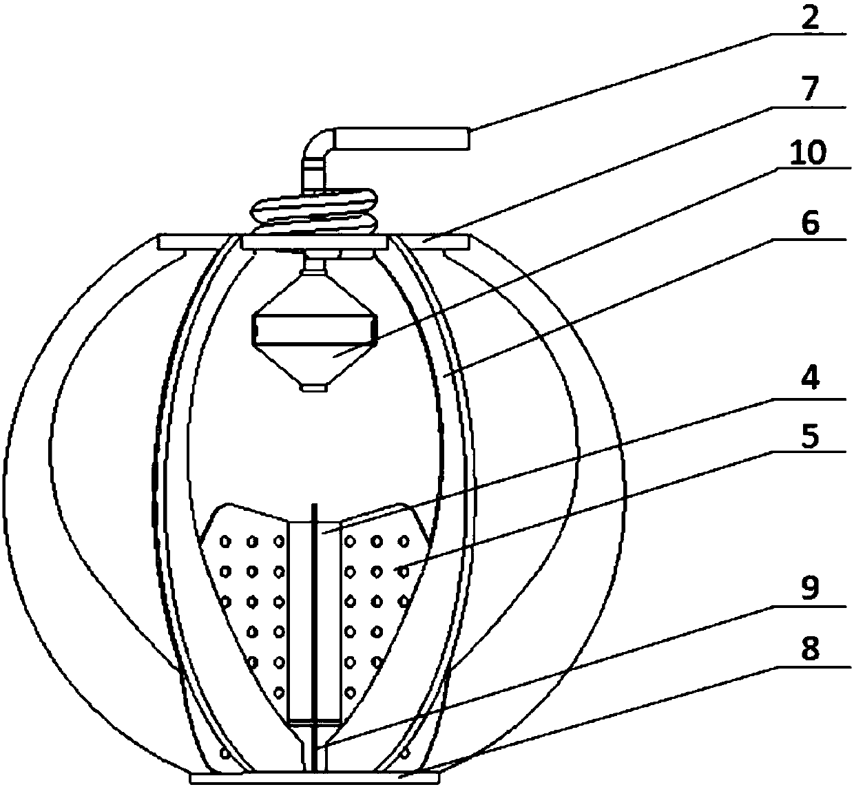
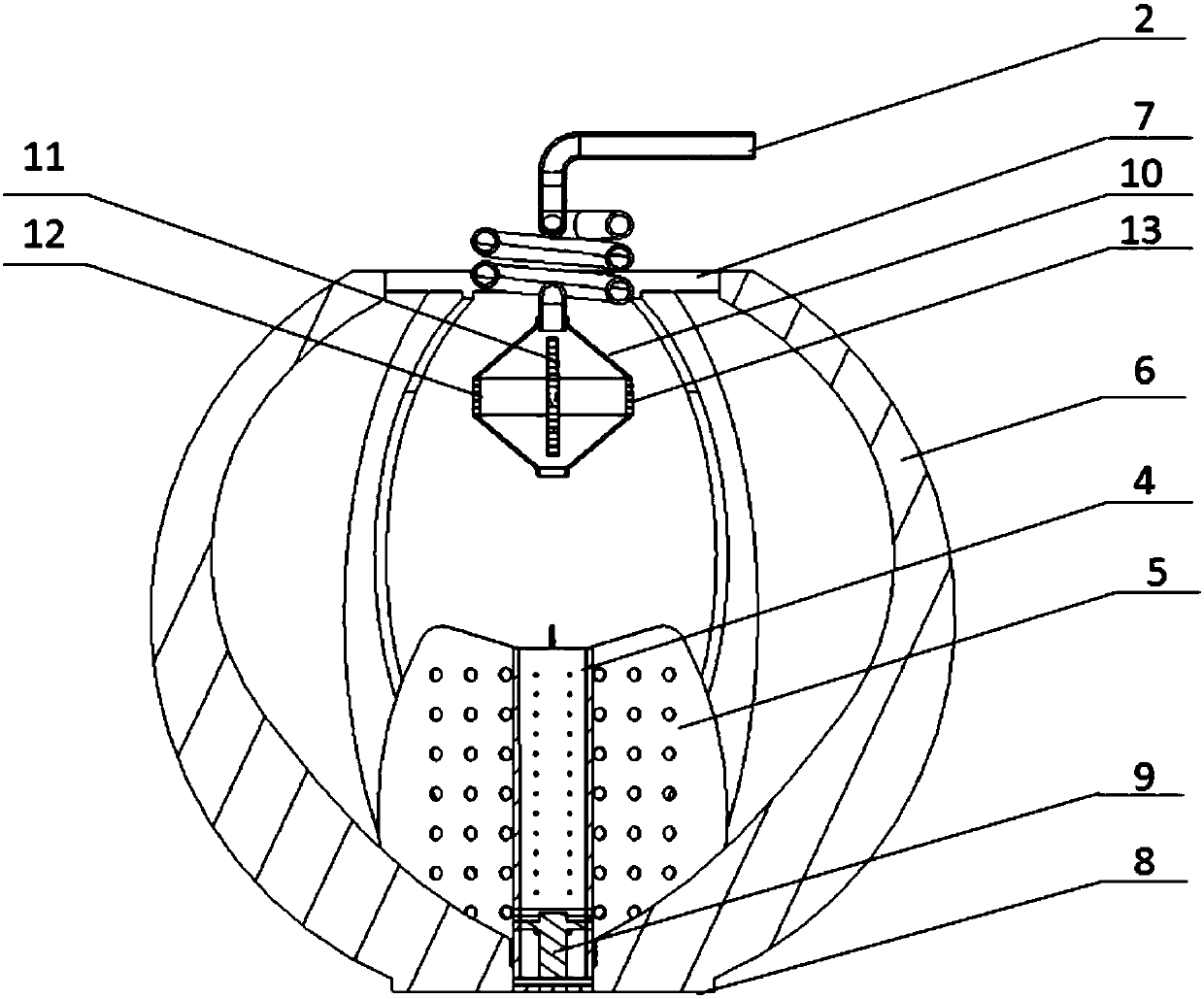
[0033] Such as Figure 1-5 Shown is a schematic diagram of a space fuel storage tank fluid management system based on electric field effects. The system includes: storage tank wall 1, exhaust pipe 2, drain / fill port 3, central cylinder 4 (upper cylinder 401, lower cylinder 402), Inner deflector 5, outer deflector 6, upper tray ring 7, lower tray 8, positive electrode rod 9, spindle-shaped container 10, positive electrode large disc 11, negative electrode small discs 12 and 13.

[0034] The center tube 4 of the space plate type surface tension fuel storage tank is composed of an upper tube 401 and a lower tube 402. There are a plurality of mm-scale small holes on the circumferential walls of the upper tube 401 and the lower tube 402. The upper tube 401 and the lower tube 402 are plugged together. Or the welded inner deflector 5 realizes upper and lower fixed connections. The interface between the upper cylinder 401 and the lower cylinder 402 and the outer peripheral surface of...


PUM


Abstract

The invention discloses a space fuel storage box fluid management system based on the electric field effect. The space fuel storage box fluid management system comprises a storage box wall, an exhaust pipe, a fluid discharging / feeding port, a center barrel, an inner deflector, an outer deflector, an upper tray ring, a lower tray, a positive electrode rod and a container, wherein the center barrel is composed of an upper barrel body and a lower barrel body. The upper barrel body and the lower barrel body are fixedly connected in an up-down mode through the inner deflector which is connected in an inserting mode or in a welding mode. The positive electrode rod connected with a positive pole of a power source is installed inside the lower barrel body, and the axis of the positive electrode rod coincides with that of the lower barrel body connected with a negative pole of the power source. A capillary screen net is installed between the lower end of the lower barrel body and the fluid discharging / feeding port. The container is composed of two revolved bodies with the upper cross sections and the lower cross sections being isosceles trapezoids, and the revolved bodies are connected together through a waist flange. Two installation round holes are symmetrically formed in the waist flange and used for installing a negative electrode wafer connected with the negative pole of the power source. A positive electrode wafer which is connected with the positive pole of the power source and parallel to the negative electrode wafer is installed inside the container. The upper end of the container is provided with an exhaust port which is fixedly connected with the exhaust pipe. The lower end of the container is provided with an air inlet.

Description

technical field [0001] The invention relates to a novel fuel storage tank fluid management system, in particular to a fuel storage tank fluid management system applied in a space microgravity environment based on an electric field effect. The present invention innovatively utilizes the electrohydrodynamic EHD concept in the space fuel storage tank, replaces the gravity field with a conservative force field formed by an electric field, and effectively strengthens the gas-liquid phase distribution of the fluid working fluid in the space fuel storage tank. Transportation and active control belong to the field of fluid management for on-orbit service. Background technique [0002] With the rapid expansion of the scale of human space development and utilization, in order for spacecraft to perform missions and meet their functional and performance requirements, the demand for fluid working fluid fuel is increasing, and its working cycle is directly affected by the consumable fuel ...

Claims


Application Information

Patent Timeline
Patent Type & Authority Patents(China)
IPC IPC(8): B67D7/76
CPCB67D7/766
Inventor 马蓉姚伟吕晓辰王超李振新
Owner CHINA ACADEMY OF SPACE TECHNOLOGY
Learn More