
Portable operation platform for optical fiber fusion welding

A technology of optical fiber fusion splicing and working platform, which is applied in the direction of optics, light guides, optical components, etc., can solve the problems of inconvenient carrying, inconvenient operator, complicated installation procedures, etc., to ensure the stability of optical fiber splicing, improve operating comfort, and operate The effect of increasing the area

Active Publication Date: 2016-08-10
INNO INSTR (CHINA) INC
View PDF7 Cites 4 Cited by
  • Summary
  • Abstract
  • Description
  • Claims
  • Application Information

AI Technical Summary

Problems solved by technology

The invention is fixed on the pole tower by fastening fixtures, and has the conditions for high-altitude fusion. The fiber fusion process can be carried out directly on the pole tower, which shortens the time for troubleshooting. However, the installation procedure of the invention is complicated and inconvenient to carry.
[0004] For field fusion splicing operations, in the prior art, there is a method of using the flat box cover of the carrying box (the box containing the optical fiber fusion splicer) to carry out field optical fiber fusion splicing. The feature is that it is easy to carry, but the area of ​​​​the carrying box cover is limited. Machine and all optical fiber processing tools before fusion are difficult, which brings a lot of inconvenience to the operation
In addition, when working on the ground, the operator needs to squat on the ground, which is laborious and inconvenient to the operator

Method used


Image

  • Portable operation platform for optical fiber fusion welding
  • Portable operation platform for optical fiber fusion welding
  • Portable operation platform for optical fiber fusion welding

Examples


Embodiment Construction

[0029] The present invention will be further described below in conjunction with the accompanying drawings.

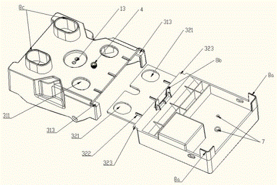
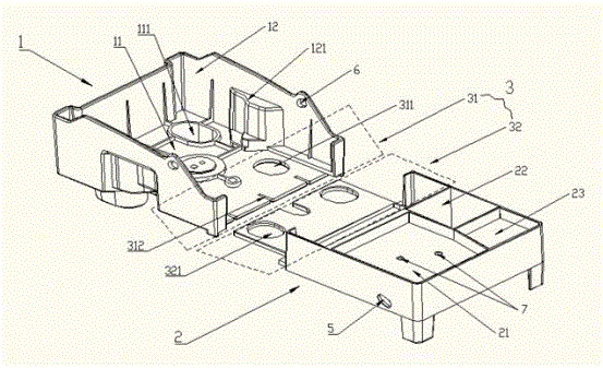
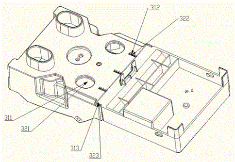
[0030] refer to figure 1 and figure 2 , the present invention provides a portable optical fiber fusion splicing platform, including an optical fiber fusion splicing platform 1 and an optical fiber cutting platform 2, wherein the optical fiber fusion splicing platform 1 is used to accommodate an optical fiber fusion splicing machine, and the optical fiber fusion splicing platform includes a fixed part 11 of the optical fiber fusion splicing machine And the optical fiber fusion splicer limit part 12, the optical fiber fusion splicer fixed part 11 is provided with the optical fiber fusion splicer placement hole 111 and the optical fiber fusion splicer locking hole 13, the size of the optical fiber fusion splicer placement hole 111 and the foot size of the optical fiber fusion splicer Adaptation, the locking hole 13 of the optical fiber fusion splicer corresponds to the ...


PUM

PropertyMeasurementUnit
The inside diameter ofaaaaaaaaaa
Pitchaaaaaaaaaa

Abstract

The invention discloses a portable operation platform for optical fiber fusion welding. The portable operation platform includes an optical fiber fusion welding platform and an optical fiber cutting platform; the optical fiber fusion welding platform accommodates an optical fiber fusion welding machine; the optical fiber cutting platform is used for optical fiber treatment before optical fiber fusion welding; the optical fiber fusion welding platform is detachably connected with the optical fiber cutting platform through a connecting portion; a tripod fixing hole is formed in the bottom of the portable operation platform; the tripod fixing hole is in matched connection with a camera tripod; and waist sling fixing holes and neck sling fixing holes are formed at side portions of the portable operation platform and are used for fixing slings connected with an operator. The portable operation platform of the invention can be used under various conditions such as high-altitude space, ground and platforms, can facilitate the operation of the operator and can better adapt to various practical requirements.

Description

technical field [0001] The invention relates to the technical field of optical fiber fusion operation accessories, in particular to a portable operation platform for optical fiber fusion. Background technique [0002] With the rapid development of the telecommunications industry, the demand for optical fiber connections has increased. In order to adapt to various optical fiber fusion splicing environments, such as high-altitude, field, and factory batch splicing, various special workbenches have been proposed in the prior art. [0003] Patent document CN201410262901.8 discloses an optical cable high-altitude welding device, which includes a welding platform, a platform bracket is fixed below the welding platform, and a left pedal strut and a right pedal strut are respectively fixed on both sides below the platform bracket. The invention is fixed on the pole tower by fastening fixtures, and has the conditions for high-altitude fusion. The fiber fusion process can be carried ...

Claims


Application Information

Patent Timeline
IPC IPC(8): G02B6/255G02B6/25
CPCG02B6/25G02B6/2553
Inventor 赵阳日
Owner INNO INSTR (CHINA) INC
Learn More