
Circulating water underground cooling device

A cooling device and circulating water technology, which is applied in water shower coolers, steam/steam condensers, direct contact heat exchangers, etc., can solve the problems of increasing air discharge and evaporation water loss, and achieve improved thermal efficiency and zero Emission and temperature reduction effects

Inactive Publication Date: 2017-07-28
张富华
View PDF6 Cites 0 Cited by
  • Summary
  • Abstract
  • Description
  • Claims
  • Application Information

AI Technical Summary

Problems solved by technology

The cooling tower of the conventional wet cooling system commonly used at present discharges a large amount of waste heat into the air through evaporation while cooling the circulating water. This heat exchange method leads to a large amount of evaporation water loss.
The cooling temperature of the circulating water has a great influence on the economic benefits of the enterprise, and the cooling method of the circulating water of the cooling tower increases the emission in the air
Therefore, the existing circulating water cooling towers on the ground are no longer suitable for the needs of social development. In order to achieve energy saving and emission reduction, circulating water cooling should use circulating water underground cooling devices

Method used


Image

  • Circulating water underground cooling device
  • Circulating water underground cooling device
  • Circulating water underground cooling device

Examples


Embodiment Construction

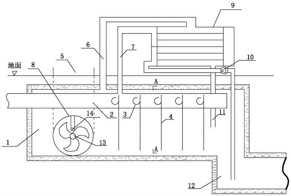
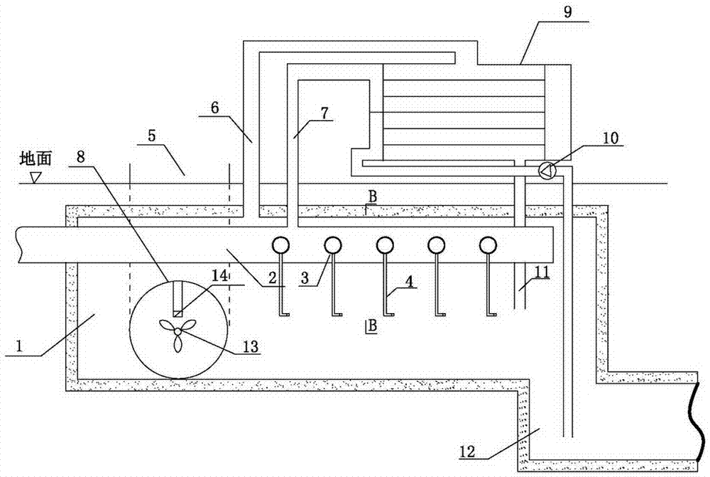
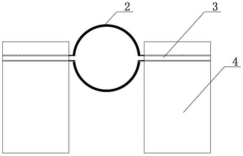
[0025] Concrete pouring a water-drying tunnel 1 at the underground constant temperature layer, there are horizontal underground cooling ducts 8 on both sides of the water-drying tunnel 1, and the ventilation ducts 8 are communicated with the ground air inlet 5. Spraying device 14 is arranged in ventilation pipe 8, and spraying device 14 is to have atomizing nozzle at the end of many drainage pipes, and spraying device 14 water is to lead from the cool water in the reservoir 12. The spraying device 14 cools down the air, and the low-temperature air is discharged into the water-drying hole 1 by the induced draft fan 13 . The main water pipe 2 is connected to the outlet of the condenser and introduced into the water-drying hole 1, the hot water in the main water pipe 2 is distributed to the branch pipe 3 to flow out, and is dissipated by the heat sink 4, and the heat sink can be connected to the flat plate type The upper part of the heat sink has an opening above the side of the ...


PUM


Abstract

The invention discloses an underground cooling device for circulating water, used at a power station, a chemical plant, a steel mill and the like. A water cooling tunnel is build in an underground constant-temperature layer, and the lower part of the water cooling tunnel is connected with a reservoir. A main water pipeline is arranged in the water cooling tunnel, a plurality of branch water pipes are arranged on the main water pipeline, the branch water pipes are connected with coolers, and the main water pipeline is connected with a circulating water pipeline at an outlet of a condenser of a steam turbine set. Circulating hot water in the main water pipeline passes the branch water pipes, is cooled by the coolers and then flows into the reservoir. A ventilation pipeline is arranged in the water cooling tunnel. The condenser is arranged on the ground, an exhaust pipeline above the water cooling tunnel is connected with the condenser, a condensed water pipe of the condenser is led into the water cooling tunnel, and a circulating water inlet of the condenser is connected to the reservoir through a pipeline. The underground cooling device for circulating water utilizes underground cold air resources to lower the temperature of circulating water, improves the thermal efficiency of the generator set and realizes damp and hot steam zero-emission.

Description

[0001] 1. Technical field [0002] The invention relates to circulating water cooling devices for power plants, chemical plants, steel mills and the like. [0003] 2. Background technology [0004] Cooling towers are used for the cooling of circulating water in existing power plants, chemical plants, and steel mills. Cooling tower is an important mass transfer equipment in the process of generating electricity in power plants. Its function is to disperse the heat of high-temperature water into the atmosphere through heat and mass exchange, and reduce the temperature of circulating water. Its cooling water mainly relies on the mixing and contacting of cold and hot fluids in the tower, and with the help of the water vapor partial pressure difference between the two liquids, the hot liquid is partially evaporated and cooled by itself. [0005] The composition of the hyperbolic natural ventilation cooling tower can be divided into two parts: the tower structure and the water spray...

Claims


Application Information

Patent Timeline
Patent Type & Authority Patents(China)
IPC IPC(8): F28B9/06F28C1/00F28F25/06
CPCF28B9/06F28C1/00F28F25/06
Inventor 张富华张旭张鹏
Owner 张富华
Learn More