Piston ring of internal combustion engine and internal combustion engine provided with piston ring

A technology for piston rings and internal combustion engines, applied to piston rings, machines/engines, mechanical equipment, etc., to achieve the effects of reducing wear, reducing wear and friction power consumption, and increasing oil film thickness

Inactive Publication Date: 2016-07-27
JIANGSU UNIV
View PDF5 Cites 0 Cited by
  • Summary
  • Abstract
  • Description
  • Claims
  • Application Information

AI Technical Summary

Problems solved by technology

[0005] However, in the internal combustion engine, the piston assembly is constantly changing from low speed to high speed, light load to heavy load, which makes the friction and wear of the cylinder liner-piston ring pair particularly prominent under extreme service conditions.
Although the micro-dimple structure with uniform depth can alleviate the friction and wear problem to a certain extent, it cannot obtain the best friction performance of the piston ring-cylinder liner pair under the condition of alternating load of the internal combustion engine.

Method used


Image

  • Piston ring of internal combustion engine and internal combustion engine provided with piston ring
  • Piston ring of internal combustion engine and internal combustion engine provided with piston ring
  • Piston ring of internal combustion engine and internal combustion engine provided with piston ring

Examples


Embodiment Construction

[0025] In order to have a clearer understanding of the technical features, purposes and effects of the invention, the specific implementation manners of the present invention will now be described with reference to the accompanying drawings, in which the same reference numerals represent the same or similar parts. The accompanying drawings are only used to illustrate the present invention, and do not represent the actual structure and true scale of the present invention.

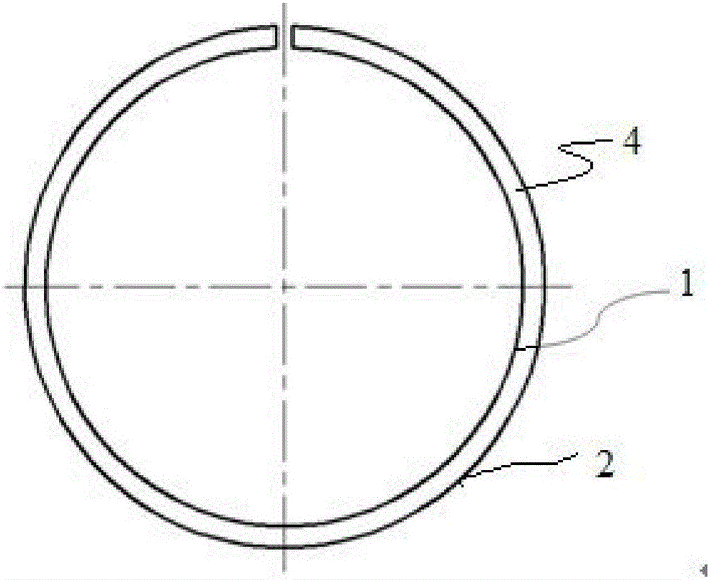
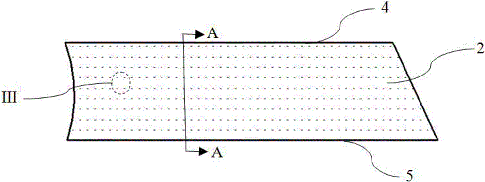
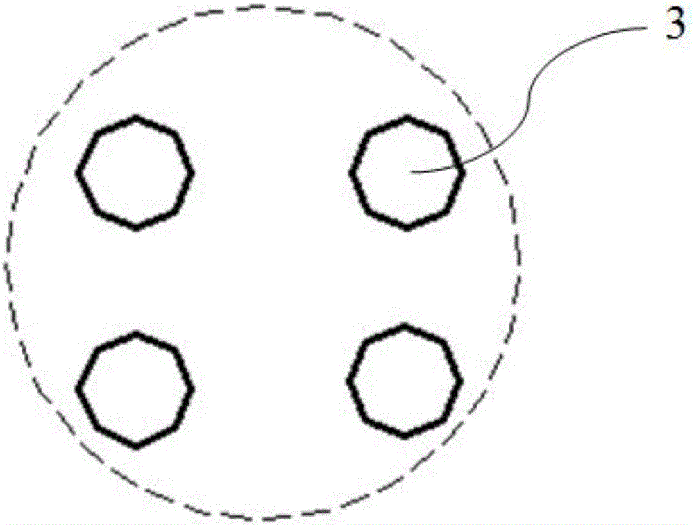
[0026] figure 1 Shown is a kind of schematic diagram of internal combustion engine piston ring of the present invention, described piston ring 1 comprises piston ring outer surface 2, piston ring upper end surface 4 and piston ring lower end surface 5; The upper end surface 4 of the piston ring and the lower end surface 5 of the piston ring are perpendicular to each other. On the outer surface 2 of the piston ring, several micro-dimple structures 3 with different depths are processed by laser machining or o...


PUM

PropertyMeasurementUnit
Radius raaaaaaaaaa
Radius raaaaaaaaaa
Maximum depthaaaaaaaaaa

Abstract

The invention relates to a piston ring of an internal combustion engine and the internal combustion engine provided with the piston ring, and belongs to the field of internal combustion engine research. The piston ring comprises a piston ring outer surface, a piston ring upper end face and a piston ring lower end face. A plurality of micro pit structures of different depths are machined in the piston ring outer surface. The depths of the micro pit structures have a gradual decrease trend from the piston ring upper end face to the piston ring lower end face. The micro pit structures are formed in the piston ring outer surface, and because the depths of the micro pit structures have the gradual decrease trend from the piston ring upper end face to the piston ring lower end face, the oil storage sizes of the micro pit structures are accordingly reduced, a wedge-shaped effect is achieved, lubricating oil overflows and is squeezed to form certain oil pressure after flowing into the pit, with the small depth, close to the piston ring lower end face, the oil film thickness is increased, the rough peak contact between two surfaces of a kinematic pair is reduced, and friction and abrasion are effectively reduced. The piston ring is novel in structure, the lubrication condition of a cylinder sleeve and the piston ring of the internal combustion engine is effectively improved, the abrasion amount and the friction power consumption are decreased, and the service life of the piston ring is prolonged.

Description

technical field [0001] The invention belongs to the field of internal combustion engine research, in particular to a piston ring of an internal combustion engine and an internal combustion engine equipped with the piston ring. Background technique [0002] In recent decades, the development of internal combustion engines has mainly focused on the control of harmful emissions and low-carbon energy-saving technologies. The cylinder liner piston ring system of the engine needs to meet the strict requirements of energy conservation and emission reduction; at the same time, various advanced combustion and emission control technologies will gradually be used in engines. With the emergence and continuous application in the world, the engine is increasingly showing a trend of small size, high strength, high power density and light weight. The application of these advanced technologies makes the key lubrication and friction pairs of the cylinder liner and piston ring of the internal c...

Claims


Application Information

Patent Timeline
IPC IPC(8): F02F5/00
CPCF02F5/00
Inventor 尹必峰俞升浩贾和坤符永宏华希俊董非
Owner JIANGSU UNIV
Why Eureka
Try Eureka