Oil separation method and oil separation device for a hydrodynamic thrust bearing

A technology of thrust bearing and hydrodynamic pressure, which is applied in the direction of bearing components, shafts and bearings, bearing cooling, etc., can solve the problems of increased space occupied by thrust bearings, increased manufacturing materials of thrust bearings, and increased working oil temperature of bearings, etc., to achieve Reduce space occupation area, reduce manufacturing cost, improve the effect of oil separation effect

Active Publication Date: 2016-08-17
DONGFANG ELECTRIC MACHINERY
View PDF4 Cites 0 Cited by
  • Summary
  • Abstract
  • Description
  • Claims
  • Application Information

AI Technical Summary

Problems solved by technology

However, in two adjacent bearing pads, since the oil outlet end of the previous bearing pad is the oil inlet end of the rear bearing pad, and the oil will become hot after being rubbed by the mirror plate, this will cause some hot oil to adhere to the mirror plate Driven by the mirror plate, it enters between the next bearing bush and the mirror plate, correspondingly reducing the amount of cold oil entering the bearing bush, not only increasing the working oil temperature of the bearing, reducing the bearing capacity of the bearing, but also easy to bearing damage
In addition, in actual use, it is usually used to increase the distance between the two bearing pads to reduce the amount of hot oil that the former bearing pad enters the rear bearing pad, but this method increases the volume of the thrust bearing accordingly, which not only leads to the The increase in the space occupied area also leads to an increase in the manufacturing materials of the entire thrust bearing and a higher cost

Method used


Image

  • Oil separation method and oil separation device for a hydrodynamic thrust bearing
  • Oil separation method and oil separation device for a hydrodynamic thrust bearing
  • Oil separation method and oil separation device for a hydrodynamic thrust bearing

Examples


Embodiment 1

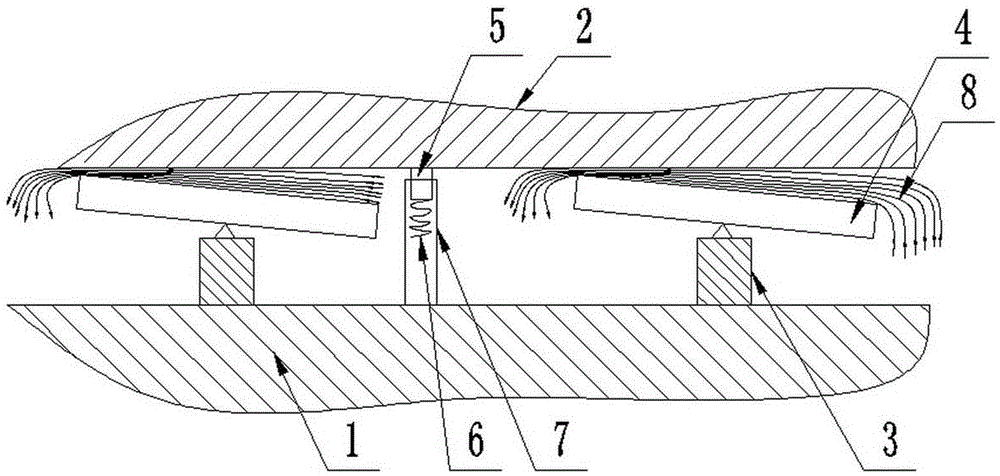
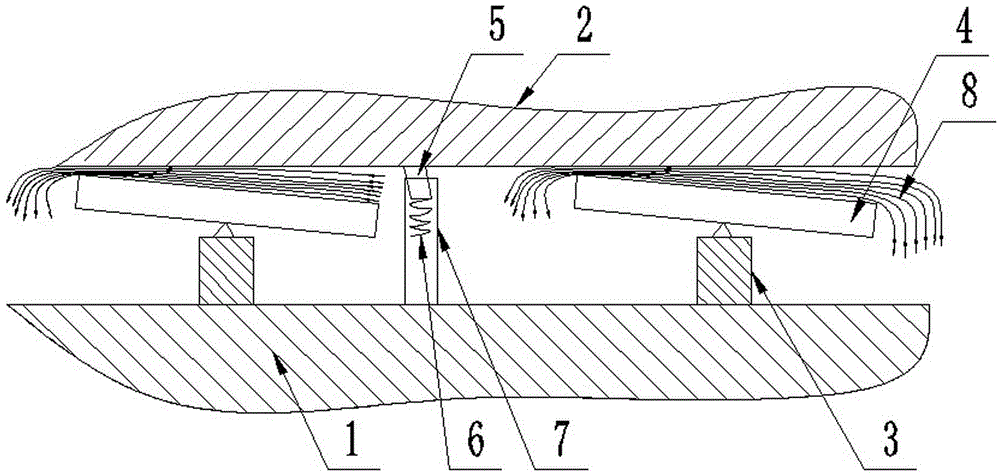
[0028] An oil separation method for a hydrodynamic thrust bearing. When the hydrodynamic thrust bearing is working, the rotating shaft in the thrust bearing drives the mirror plate 2 to rotate. At this time, cold oil enters the bearing bush 4 and the mirror plate 2 from the oil inlet end of the bearing bush 4 Between, and under the driving of the rotating mirror plate 2, an oil film is formed between the bearing bush 4 and the mirror plate 2. Since there is friction between the rotating mirror plate 2 and the oil film, the friction of the cold oil on the rotating mirror plate 2 It turns into hot oil and flows from the oil outlet end of the bearing pad 4 to the oil inlet end of the next bearing pad 4 driven by the mirror plate 2. Before the hot oil enters the last bearing pad 4, the An oil separation device is set between the last bearing bush 4 to cooperate with the working surface of the mirror plate 2 to make the hot oil flow into the oil groove 1 below the bearing bush 4, an...

Embodiment 2

[0030] An oil separation device for a hydrodynamic thrust bearing, comprising a rotating shaft, a mirror plate 2, a bearing seat 3 and a bearing bush 4, the rotating shaft is fixed in the oil tank 1 and fixedly connected with the mirror plate 2 to drive the mirror plate 2 to rotate, and the bearing seat 3 Fixed in the oil tank 1, the number of bearing pads 4 is multiple, distributed around the rotating shaft through the bearing seat 3, and the bearing pads 4 are arranged obliquely under the working surface of the mirror plate 2, and form a wedge-shaped gap with the mirror plate 2 in the forward direction. The large opening side 8 of the wedge-shaped gap is the oil inlet end, and the small opening side of the wedge-shaped gap is the oil outlet end; the oil separation device is arranged between two adjacent bearing bushes 4, and the oil separation device includes an oil separation plate 5 and a support frame 7. The support frame 7 is fixed on the bottom of the oil tank 1, the low...

Embodiment 3

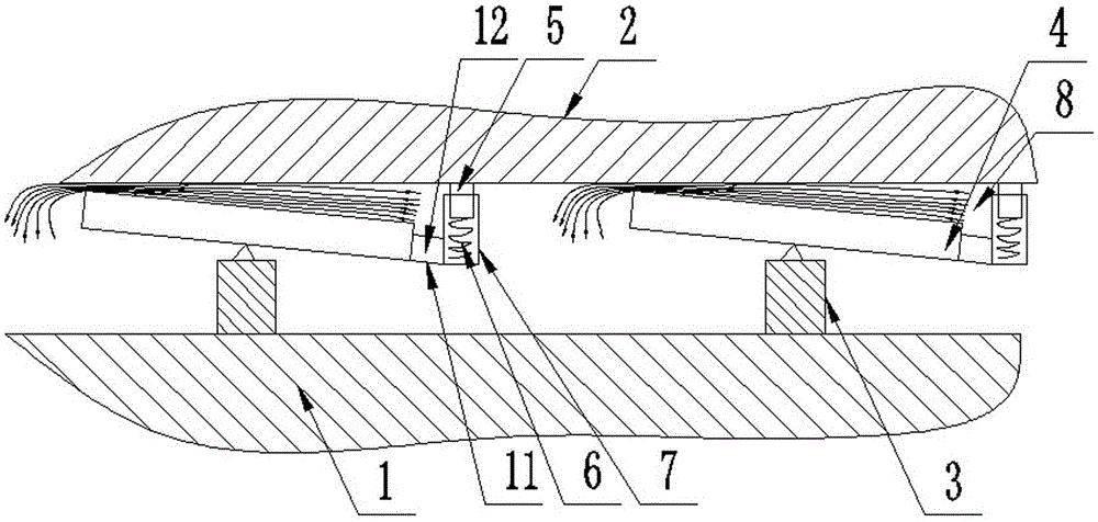
[0035] This embodiment is basically the same as the above-mentioned embodiment, the main difference is that: the support frame 7 is fixed on the bearing bush 4 on the side of the large opening of the wedge-shaped gap through the connecting piece 11, and there is an oil inlet passage 12 between the support frame 7 and the bearing bush 4. Oil enters the bearing bush 4 from the oil inlet channel 12 between the support frame 7 and the bearing bush 4 . In the existing thrust bearings, the bearing bush 4 can automatically and slightly adjust the thickness of the oil film according to the bearing load. Therefore, the structure in which the support frame 7 is fixed on the oil inlet side of the bearing bush 4 can also automatically and slightly adjust the oil separator 5 and the mirror. Contact force between plates 2. However, the above-mentioned embodiment is preferred, and is not limited to the above-mentioned preferred embodiment. For example, the support frame 7 can be arranged in ...


PUM


Abstract

The invention discloses an oil removal method for a liquid dynamic pressure thrust bearing. The oil removal method comprises the following steps: when the liquid dynamic pressure thrust bearing is working, cold oil enters the part between a bearing bush and a thrust runner plate from the oil inlet end of the bearing bush, and becomes hot oil under the friction of the rotating thrust runner plate to flow out from the oil outlet end of the bearing bush, the hot oil flows towards the oil inlet end of the next bearing bush along with the rotation of the thrust runner plate, and before the hot oil enters the next bearing bush, an oil removal device is arranged and matched with the working surface of the thrust runner plate, so that the hot oil flows in an oil tank below the bearing bush. The invention further discloses the oil removal device used in the oil removal method, the oil removal device is arranged between the two adjacent bearing bushes, and is fixedly arranged in the oil tank below the working surface of the thrust runner plate. According to the oil removal method and the oil removal device, not only can the size of the overall thrust bearing be reduced, but also the amount of hot oil entering the bearing bushes can be decreased, the amount of cold oil flowing in the bearing bushes can be increased, and the purpose of improving the bearing capacity of the bearing can be achieved.

Description

technical field [0001] The invention belongs to the technical field of sliding bearings for mechanical products, and in particular relates to an oil separation method and an oil separation device for a hydrodynamic thrust bearing. Background technique [0002] In the prior art, the hydrodynamic thrust bearing is mainly composed of a rotating shaft, a mirror plate, a bearing bush and a bearing seat. The rotating shaft and the mirror plate are fixedly connected to drive the mirror plate to rotate. There are multiple bearing bushes distributed around the rotating shaft, and the bearing bushes are arranged obliquely. Under the working surface of the mirror plate, and turn forward to form a wedge-shaped gap with the mirror plate. The large opening side of the wedge-shaped gap is the oil inlet end, and the small opening side of the wedge-shaped gap is the oil outlet end. The bearing seat is fixed in the oil groove and connected with the bearing bush. When in use, driven by the rot...

Claims


Application Information

Patent Timeline
Patent Type & Authority Patents(China)
IPC IPC(8): F16C37/00F16C33/02
Inventor 钟海权欧阳宁东杨培平赵永智
Owner DONGFANG ELECTRIC MACHINERY
Why Eureka
Try Eureka