Tapered roller bearing and power transmission device

a technology of tapered roller bearings and transmission devices, which is applied in the direction of roller bearings, mechanical equipment, gearing details, etc., can solve the problems of insufficient sliding friction resistance reduction, and achieve the effect of increasing the thickness of an oil film and reducing the contact surface pressur

Active Publication Date: 2018-05-10
JTEKT CORP
View PDF0 Cites 1 Cited by
  • Summary
  • Abstract
  • Description
  • Claims
  • Application Information

AI Technical Summary

Benefits of technology

The patent aims to reduce the pressure between the inner ring's rib and the tapered roller in a tapered roller bearing while increasing the thickness of the oil film between them.

Problems solved by technology

Thus, the amount of reduction in the sliding frictional resistance may be insufficient depending on what length the radius of curvature is set to.

Method used


Image

  • Tapered roller bearing and power transmission device
  • Tapered roller bearing and power transmission device
  • Tapered roller bearing and power transmission device

Examples


Embodiment Construction

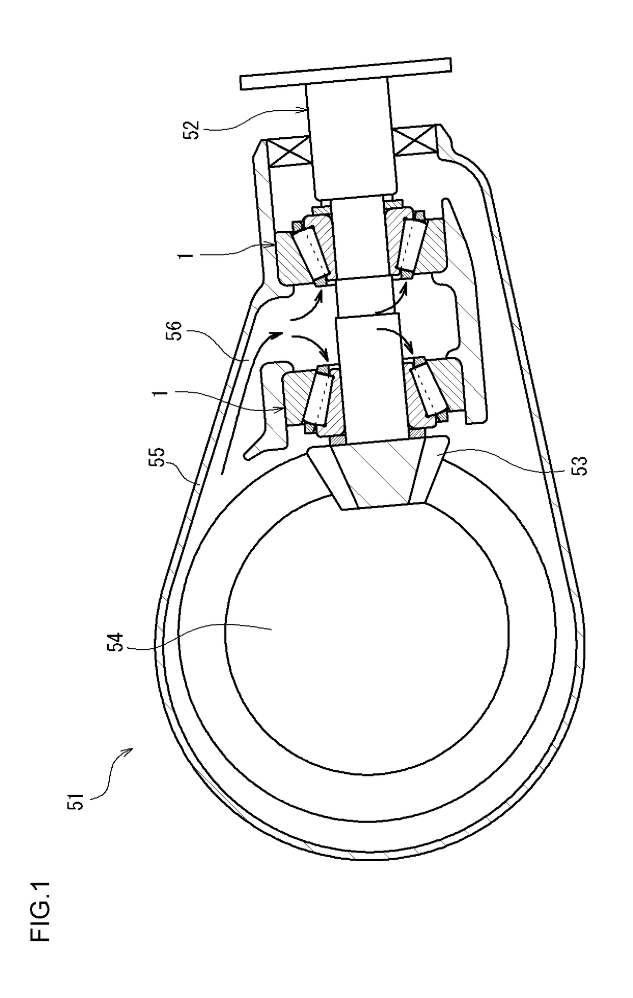
[0015]Below, an embodiment of the invention is described with reference to the drawings. FIG. 1 is a cross-sectional view of a differential device 51 having a pair of tapered roller bearings according to the embodiment of the invention. The differential device 51 is mounted in a power transmission path that transmits the output of a vehicle engine. The differential device 51 transmits the output of the engine to drive shafts (not illustrated) located to both sides (both sides in the direction perpendicular to the plane of the paper including FIG. 1) of the differential device 51.

[0016]The differential device 51 includes a pinion shaft (a power transmission shaft) 52, a pinion gear 53, a differential gear mechanism 54, and a housing 55 that houses the pinion shaft 52, the pinion gear 53, and the differential gear mechanism 54. The pinion shaft 52 rotates along with a propeller shaft (not illustrated) that transmits the output of the engine. The pinion gear 53 is provided at an end of...


PUM


Abstract

A tapered roller bearing includes an inner ring with a large rib, an outer ring, and multiple tapered rollers. Each of the tapered rollers has, at its axial end, a large end face that is a convex surface. The large rib has a rib face that is a concave surface and that is in contact with the large end face. When a distance from a position of contact between the large end face and the rib face to a cone center of the corresponding tapered roller is defined as R, a curvature radius of the large end face is defined as Rr, and a curvature radius of the rib face is defined as Ri, an inequality represented by 2≤(Ri −R) / (R−Rr)≤10 is satisfied, where Rr<R<Ri.

Description

INCORPORATION BY REFERENCE[0001]The disclosure of Japanese Patent Application No. 2016-219768 filed on Nov. 10, 2016 including the specification, drawings and abstract, is incorporated herein by reference in its entirety.BACKGROUND OF THE INVENTION1. Field of the Invention[0002]The invention relates to a tapered roller bearing and a power transmission device.2. Description of the Related Art[0003]Tapered roller bearings have a large load capacity and high rigidity, as compared to other types of rolling bearings of the same size, and are therefore widely used. In one example, tapered roller bearings are used in drive transmission devices such as a transmission and differential of a vehicle.[0004]FIG. 5 is a cross-sectional view of a tapered roller bearing according to the related art. This tapered roller bearing includes an inner ring 101, an outer ring 102, multiple tapered rollers 103, and an annular cage 104. The tapered rollers 103 are provided between the inner ring 101 and the ...

Claims


Application Information

Patent Timeline
Patent Type & Authority Applications(United States)
IPC IPC(8): F16C33/58F16C19/36
CPCF16C33/585F16C19/364F16C2326/06F16C33/366F16C2361/61F16H57/0424F16H57/0471F16H57/0493F16C19/225F16C19/548F16C2240/70
Inventor MURATA, JUNJIKAMAMOTO, SHIGEOSHISHIHARA, YUKI
Owner JTEKT CORP
Why Eureka
Try Eureka