Fixed Constant Velocity Universal Coupling

A technology for universal couplings and couplings, which is applied in the direction of couplings, elastic couplings, and rotating parts that resist centrifugal force. Effect of less torque loss

Active Publication Date: 2021-02-19
NTN CORP
View PDF5 Cites 0 Cited by
  • Summary
  • Abstract
  • Description
  • Claims
  • Application Information

AI Technical Summary

Problems solved by technology

[0002] For example, on the drive shaft for the front part of a motor vehicle, a sliding constant velocity universal shaft that can be axially displaced at a working angle is usually installed on the inner disc side (differential side) although the maximum operating angle is relatively small. For the coupling, as far as the outer disc side (wheel side) is concerned, since the wheel turns, it is equipped with a fixed constant velocity universal joint that cannot be displaced in the axial direction although it can have a large working angle

Method used


Image

  • Fixed Constant Velocity Universal Coupling
  • Fixed Constant Velocity Universal Coupling
  • Fixed Constant Velocity Universal Coupling

Examples


Embodiment Construction

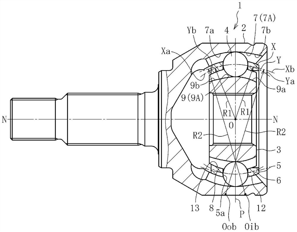
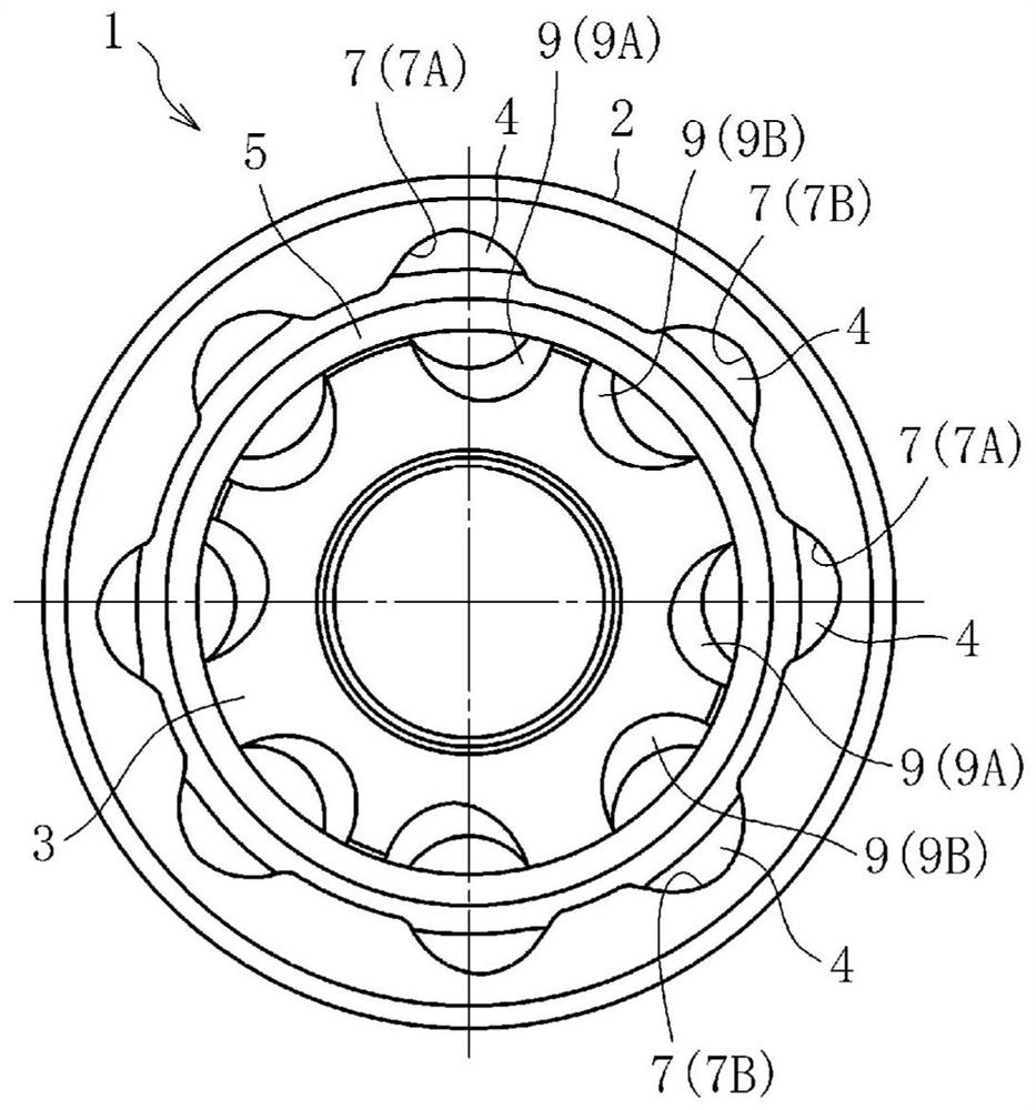
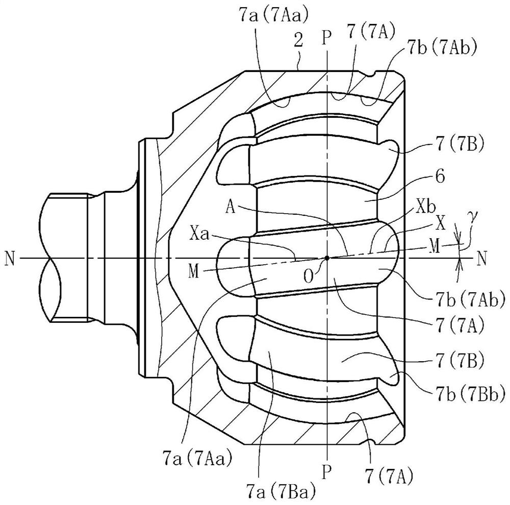
[0034] Based on Figure 1~ Figure 10 One embodiment of the present invention will be described. Figure 1a It is a partial longitudinal sectional view of the fixed type constant velocity universal joint according to this embodiment, Figure 1b is the right side view. The constant velocity universal joint 1 is mainly composed of an outer joint member 2 , an inner joint member 3 , balls 4 and a cage 5 . Such as Figure 1b2 and 3, the respective eight raceway grooves 7, 9 of the outer coupling member 2 and the inner coupling member 3 are formed to be inclined in the circumferential direction with respect to the axis N-N of the coupling, and The inclination directions of the upwardly adjacent track grooves 7A, 7B and 9A, 9B are opposite to each other. Further, eight balls 4 are arranged at intersections of the paired track grooves 7A, 9A, 7B, 9B of the outer joint member 2 and the inner joint member 3 . exist Figure 1a Among them, regarding the raceway grooves 7 and 9, respec...


PUM


Abstract

In the fixed constant velocity universal joint, the raceway groove of the outer coupling member is composed of the first raceway groove part (7a) on the inner side and the second raceway groove part (7b) on the opening side , the first raceway groove portion (7a) has a ball track centerline (Xa) with a single curvature radius (R1), and the ball track centerline (Xa) has no deviation in the axial direction relative to the coupling center (O). The center of curvature shifted, the plane (M) containing the centerline of the ball track (Xa) and the center of the coupling (O) is inclined relative to the axis of the coupling (N‑N), and the direction of inclination of the plane (M) The first raceway grooves (7a) adjacent to each other in the circumferential direction are formed in opposite directions, and the end (A) of the ball track centerline (Xa) of the first raceway grooves (7a) is located The center (O) of the device is close to the opening side, and the ball track centerline (Xb) of the second raceway groove (7b) is connected to the end (A), including the shaft coupling in the state of the working angle of 0°. Based on the plane (P) perpendicular to the center of the coupling (O) and the axis (N‑N) of the coupling, the ball track centerline (Y) of the raceway groove of the inner coupling member and the outer coupling member The ball track centerlines of the paired raceway grooves are formed in mirror-image symmetry, and are characterized in that the ball track centerline (Xb) of the second raceway groove portion (7b) has a single curvature radius (R2) and has a The axis (N-N) of the hub is radially offset from the center of curvature, and the radius of curvature (R2) is set larger than the radius of curvature (R1).

Description

technical field [0001] The present invention relates to a fixed constant velocity universal joint, in particular, to a fixed constant velocity universal joint that allows only angular displacement between two shafts on the drive side and the driven side, and is used in power transmission systems of motor vehicles and various industrial machines. Type constant velocity universal joint. Background technique [0002] For example, on the drive shaft for the front part of a motor vehicle, a sliding constant velocity universal shaft that can be axially displaced at a working angle is usually installed on the inner disc side (differential side) although the maximum operating angle is relatively small. For the coupling, on the outer disc side (wheel side), since the wheels steer, a fixed constant velocity universal joint that cannot be displaced in the axial direction is incorporated although it can have a large operating angle. [0003] A fixed constant velocity universal joint of...

Claims


Application Information

Patent Timeline
Patent Type & Authority Patents(China)
IPC IPC(8): F16D3/2245
CPCF16D3/2245F16D2003/22306F16D2003/22309Y10S464/906F16D3/224
Inventor 藤尾辉明船桥雅司
Owner NTN CORP
Why Eureka
Try Eureka