Power module and manufacturing method therefor

A technology of power module and manufacturing method, which is applied in semiconductor/solid-state device manufacturing, electrical equipment structural parts, electrical components, etc., can solve the problems of difficult to make a very large specific surface area, heavy weight, and reduced thermal conductivity.

Active Publication Date: 2016-07-06
DELTA ELECTRONICS INC
View PDF8 Cites 5 Cited by
  • Summary
  • Abstract
  • Description
  • Claims
  • Application Information

AI Technical Summary

Problems solved by technology

[0008] 1. Since the heat sink is usually formed by extruding metal such as copper, it is heavy and difficult to process. It is difficult to process short and dense, and it is difficult to make a very large specific surface area. Therefore, it is more suitable for modules with large volume and height. , is not conducive to the miniaturization of the product
And, because the fins of the heat sink are long, it is easy to contact with other electronic components, causing a short circuit
[0009] 2. The power element and the radiator are combined by spring clips. Due to the use of spring clips, the space utilization rate of the device becomes extremely low, which does not meet our requirements for power density.
Moreover, for reliable fixed connection, the power module is usually designed to have a thicker sealing material, and the power device itself has a higher

Method used


Image

  • Power module and manufacturing method therefor
  • Power module and manufacturing method therefor
  • Power module and manufacturing method therefor

Examples


no. 1 example

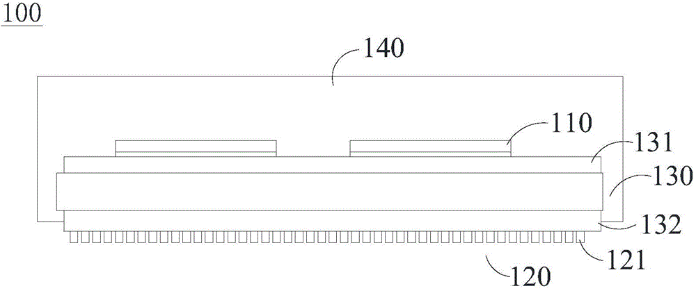
[0033] Please refer to image 3 As shown, a preferred embodiment of the present application provides a power module 100 , such as a power converter, which includes a substrate 130 , a power device 110 and an organic heat dissipation mechanism 120 . The substrate 130 has an opposite upper surface 131 and a lower surface 132. The power device 110 can be a MOSFET (such as a common SiMOSFET, GaN MOSFET, etc.), a diode, an IGBT, etc. In this embodiment, the power device 110 is a power chip. The power device 110 is bonded to the upper surface 131 of the substrate 130 . Wherein: the organic heat dissipation mechanism 120 includes a plurality of organic heat dissipation protrusions (fin) 121, and the organic heat dissipation mechanism 120 is located on the upper surface 131 side of the substrate 130 or the lower surface 132 side of the substrate 130 to dissipate the heat generated by the power device 110 Conducted to the outside through the substrate 130 and the organic heat dissipat...

no. 2 example

[0046] refer to Figure 6 The heat dissipation mechanism of the power module of this embodiment is different from that of the first embodiment in that: the lower surface 132 of the substrate 130 is pasted with a thermal adhesive 150 with a thermal spread 160, and the thermal spread 160 can usually be It is made of materials such as metal (copper / aluminum, etc.), graphite, and ceramics, and an organic heat dissipation mechanism 120 is provided on the windward side of the temperature uniform block 160 (the side away from the substrate 130 ). Other parts of the second embodiment are substantially the same as those of the first embodiment, and will not be repeated here.

no. 3 example

[0048] refer to Figure 7 The heat dissipation mechanism of the power module of this embodiment is different from the first embodiment in that: the organic heat dissipation mechanism 120 also includes a metal heat dissipation part 123, which is pasted on the lower surface 132 of the substrate through a thermally conductive adhesive 150, and the organic heat dissipation raised part 121 is formed on the lower surface of the metal heat dissipation part 123 . In this embodiment, the metal heat dissipation part 123 can be an existing heat sink (such as a heatsink), which includes a plurality of heat dissipation fins 124 . The organic heat dissipation protruding portion 121 is formed on the lower surface of the heat dissipation fins 124 by, for example, dispensing process. The metal heat dissipation part 123 can further expand the heat dissipation area. By partially disposing the organic heat dissipation protruding portion 121 under the existing common heat sink, the space can be ...


PUM

PropertyMeasurementUnit
Thermal conductivityaaaaaaaaaa

Abstract

The invention provides a power module and a manufacturing method therefor. The power module comprises a substrate, at least one power device, and an organic heat dissipation mechanism. The substrate is provided with an upper surface and a lower surface. The organic heat dissipation mechanism comprises a plurality of organic heat dissipation convex parts, and the organic heat dissipation mechanism is located at a side of the upper surface or the lower surface of the substrate, so as to conduct the heat generated by the power device to the outside. Because the organic heat dissipation mechanism can manufacture a larger surface area, the organic heat dissipation mechanism can greatly reduce the heat exchange thermal resistance between the organic heat dissipation mechanism and an environment, thereby improving the heat dissipation performance of the heat exchange of the organic heat dissipation mechanism and the environment. Therefore, the power module can reduce the height of the organic heat dissipation mechanism under the condition that the normal heat dissipation of the power module is guaranteed, reduces the occupied space, and is of great significance to the implementation of the miniaturization of the power module.

Description

technical field [0001] The present application relates to power modules, in particular to power modules with heat dissipation mechanisms. Background technique [0002] High efficiency, high power density and high reliability have always been the industry's requirements for power modules, especially power converters. High efficiency means reducing energy consumption, which is conducive to energy saving, emission reduction, environmental protection, and reduced use costs. High power density means small size and light weight, reducing transportation costs and space requirements, thereby reducing construction costs. High reliability means longer service life and maintenance costs. [0003] But these three indicators pursued by the industry are closely related to good thermal management. First, at a lower operating temperature, the on-state loss of power modules such as Metal-Oxide-Semiconductor Field-Effect Transistor (MOSFET) will be reduced, which is beneficial to the impro...

Claims


Application Information

Patent Timeline
IPC IPC(8): H01L23/12H01L21/50H01L23/367
CPCH01L23/3735H01L23/3737H01L23/4334H01L23/49568H01L2924/181H01L2924/0002H01L24/16H01L24/29H01L24/32H01L24/48H01L24/73H01L24/83H01L25/072H01L2224/0401H01L2224/04042H01L2224/16227H01L2224/16245H01L2224/291H01L2224/32225H01L2224/32245H01L2224/48227H01L2224/48247H01L2224/73265H01L2224/8384H01L2224/83851H01L2924/10253H01L2924/1033H01L2924/13055H01L2924/13091H01L23/3677H01L2924/00012H01L2924/014H01L2924/00014H01L2924/00H05K7/209
Inventor 洪守玉陈彦霖赵振清
Owner DELTA ELECTRONICS INC
Why Eureka
Try Eureka