A garbage pyrolysis gasifier

A technology for pyrolysis, gasification and waste, applied in incinerators, lighting and heating equipment, combustion types, etc., can solve the problems of large floor space, secondary pollution, dust pollution, etc. The effect of oxin generation and easy operation

Active Publication Date: 2019-01-18
CHINESE RES ACAD OF ENVIRONMENTAL SCI
View PDF6 Cites 0 Cited by
  • Summary
  • Abstract
  • Description
  • Claims
  • Application Information

AI Technical Summary

Problems solved by technology

Landfill treatment covers a large area, and the leachate and odorous gas produced by it will cause serious secondary pollution to the soil, groundwater and surrounding air environment, and damage the ecological environment; composting technology requires pre-treatment of garbage, requiring high organic matter The composting process needs to occupy a large area of ​​land, and at the same time, polluting gases and leachate will be produced. Improper treatment will cause serious environmental pollution; the essence of incineration is to oxidize organic waste into inert waste under high temperature and sufficient oxygen supply conditions. Gaseous substances and inorganic non-combustible substances form stable solid residues. During incineration, a large amount of odorous, sulfur-containing and other toxic gases will be released. Dust and fine particles will fly with the wind, causing sulfur dioxide suspended particles in the air to exceed the standard, and frequent dust pollution caused by acid rain. Occurrence, and will produce a large amount of strong carcinogen dioxin, which is currently the main restrictive factor restricting combustion treatment

Method used


Image

  • A garbage pyrolysis gasifier

Examples


Embodiment Construction

[0017] specific implementation plan

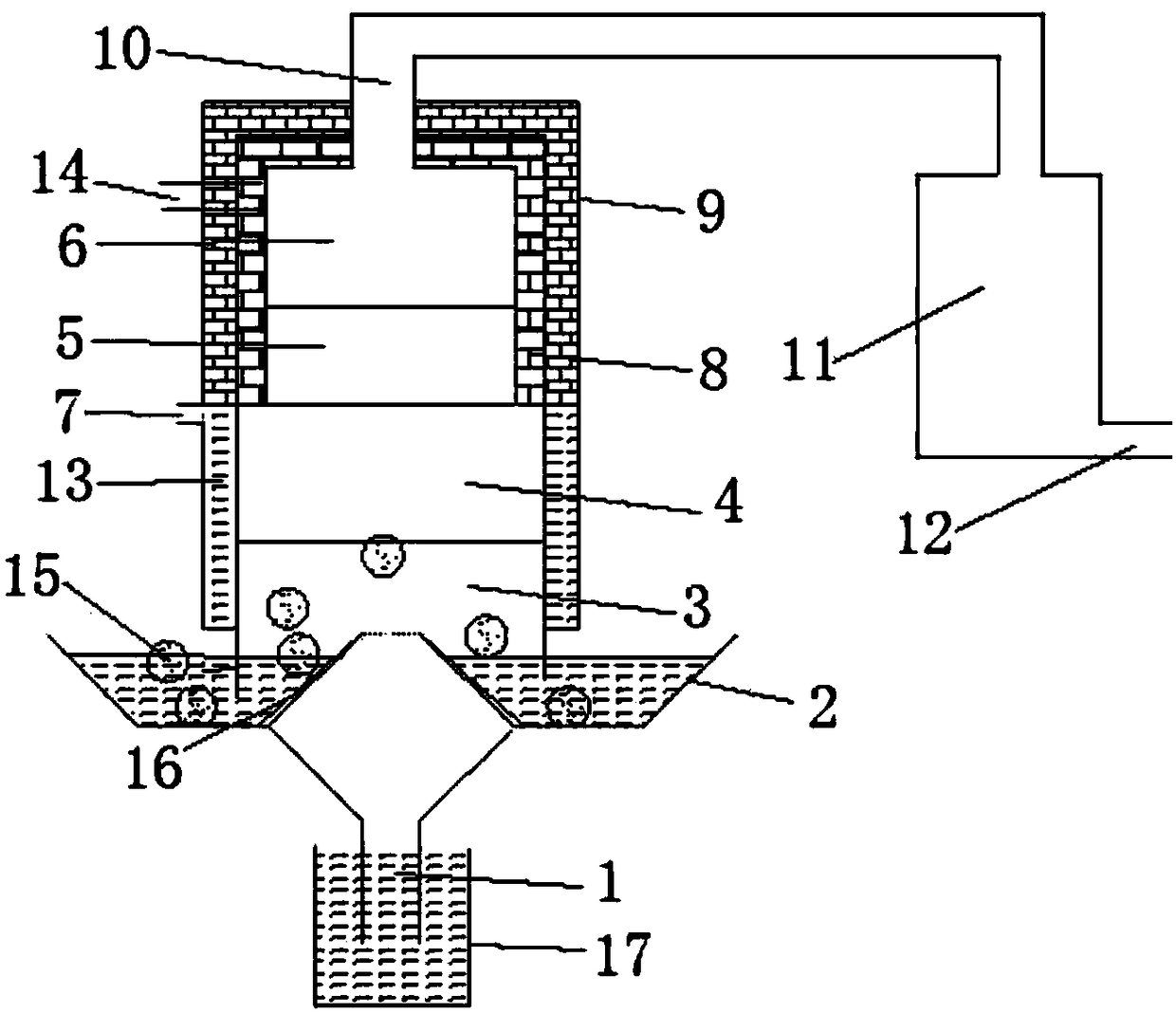
[0018] The garbage pyrolysis gasification furnace of the present invention enables materials to be pyrolyzed under anaerobic or oxygen-deficient conditions, and finally converted into high-temperature combustible gas, tar, and solid residues. Due to its pyrolysis and gasification at a high temperature above 1000°C, the amount of dioxin produced is very small, far below the national standard, and a secondary combustion chamber is connected to further process the dioxin formed by cooling. At the same time, it can be processed at any time, The characteristics of thorough treatment make it avoid the generation of stench and save a lot of land. The high-temperature gas collects tar through electric coke capture, and the remaining gas is used for power generation and brick burning, which can maximize the utilization of resources.

[0019] The present invention will be described in detail below in conjunction with the accompanying drawings.

[0...


PUM


Abstract

The invention discloses a garbage pyrolysis gasification furnace. A base of a furnace body is arranged in an ash pan. An air and steam inlet channel is formed in the center of the ash pan. An air and steam inlet of the air and steam inlet channel communicates with the interior of the garbage pyrolysis gasification furnace. An air and steam outlet is formed in the top end of the air and steam inlet channel, and the lower end of the air and steam inlet channel is connected with an air blower. A pyrolysis gasification chamber in the garbage pyrolysis gasification furnace is provided with an ash layer, a combustion gasification chamber, a destructive distillation layer and a drying layer from bottom to top. The combustion gasification chamber is provided with an ignition opening. A pyrolysis gasification gas outlet is formed in the drying layer and is connected with a secondary combustion chamber. A feeding opening is formed in the top of the garbage pyrolysis gasification furnace. A scraper is welded to the ash pan, the ash pan is driven by a motor to rotate, ash entering the ash pan is brought out by the scraper, and two rows of small gas holes are formed in the two sides of the scraper. According to the garbage pyrolysis gasification furnace, the optimal efficiency of garbage pyrolysis gasification can be achieved, and the garbage pyrolysis gasification furnace is more economical and environment-friendly.

Description

technical field [0001] The invention belongs to the field of solid waste treatment and resource utilization, and in particular relates to a garbage pyrolysis gasifier. Background technique [0002] At present, there are four main ways to deal with urban waste in various countries in the world: landfill, composting and incineration, and pyrolysis and gasification. Landfill treatment covers a large area, and the leachate and odorous gas produced by it will cause serious secondary pollution to the soil, groundwater and surrounding air environment, and damage the ecological environment; composting technology requires pre-treatment of garbage, requiring high organic matter The composting process needs to occupy a large area of ​​land, and at the same time, polluting gases and leachate will be produced. Improper treatment will cause serious environmental pollution; the essence of incineration is to oxidize organic waste into inert waste under high temperature and sufficient oxygen...

Claims


Application Information

Patent Timeline
Patent Type & Authority Patents(China)
IPC IPC(8): F23G5/027F23G5/14
CPCF23G5/0276F23G5/14
Inventor 席北斗祝超伟李鸣晓侯佳奇姜永海贾璇郝艳吕宁磬
Owner CHINESE RES ACAD OF ENVIRONMENTAL SCI
Why Eureka
Try Eureka