
Tin tetrachloride production device with wave tube reactor

A technology of tin tetrachloride and production device, applied in directions such as tin chloride, tin halide, etc., can solve problems such as heat release, influence reaction speed, difficulty, etc., and achieve increased reaction contact area, improved reaction speed, environmental The effect of pollution reduction

Inactive Publication Date: 2016-07-06
NANYANG NORMAL UNIV
View PDF7 Cites 0 Cited by
  • Summary
  • Abstract
  • Description
  • Claims
  • Application Information

AI Technical Summary

Problems solved by technology

① and ② are not only expensive, but also have the problem of uneven heating or difficult discharge of exothermic heat, which is also one of the main reasons for the amplification effect in chemical production; in addition, chemical reactions often require stirring, which faces the problem of shaft sealing. Especially for high-pressure, high-temperature reactions and reactions that require high-speed stirring, it is more difficult or even impossible to solve the problem of shaft sealing.
③Although it can overcome the above shortcomings of ① and ②, it does not have a good ability to mix the reactants, so it needs to be equipped with a reactant stirring and mixing device
Therefore, the low-temperature reaction has the problem that the reaction speed is slow, and it can only be produced intermittently. Its advantage is that the impurity content of the crude product is low, but redistillation cannot be avoided in order to meet the requirements of the national standard 622-89; although the high-temperature reaction can be produced continuously, However, due to the large density difference between tin liquid and chlorine gas, the speed of chlorine bubbles escaping tin liquid is fast, which will inevitably affect the reaction speed.
Furthermore, supplementing tin nuggets easily causes chlorine and tin tetrachloride to pollute the environment

Method used


Image

  • Tin tetrachloride production device with wave tube reactor

Examples


Embodiment Construction

[0023] In order to make the content of the present invention more obvious and easy to understand, the present invention will be described in detail below with reference to specific embodiments.

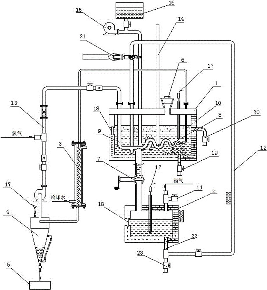
[0024] As shown in the figure, the tin tetrachloride production device with a wave tube reactor includes a tin melting furnace 1, a pressurized tank 2, a condensation pipe 3, a chlorine storage tank, a cyclone tank 4 and a product storage tank 5. The top of the tin furnace 1 is provided with a feeding port 6, the bottom of the tin melting furnace 1 is connected with the pressurized tank 2 through a tin liquid feeder 7, and a wave tube reactor is provided inside the tin melting furnace 1, and the wave tube reactor includes a pipe body. The reaction pipe 8 is a wave-shaped pipe body, two inlet pipes 9 arranged at one end of the reaction pipe 8, and a product outlet pipe 10 arranged at the other end of the reaction pipe 8; the bottom of the pressurized tank 2 is connected with a tin liqui...


PUM


Abstract

The invention discloses a tin tetrachloride production device with a wave tube reactor. The tin tetrachloride production device comprises a tin smelting furnace, a pressurizing tank, a condensing tube, a chlorine gas storage tank, a cyclone separating tank and a product storage tank, wherein the tin smelting furnace is connected to the pressurizing tank; the interior of the tin smelting furnace is provided with the wave tube reactor; the wave tube reactor comprises a reaction pipeline with a tube body as a wave tube body, two inlet tubes and a product outlet tube; the bottom of the pressurizing tank is connected with a tin liquor feeding tube; the tail end of the tin liquor feeding tube is connected to any inlet tube of the wave tube reactor; the outlet of the chlorine gas storage tank is connected with a tee joint; one outlet of the tee joint is connected to the other inlet tube of the wave tube reactor through the chlorine gas inlet tube; another outlet of the tee joint is connected to the top of the cyclone separating tank; the product outlet tube of the wave tube reactor is connected to the cyclone separating tank through the condensing tube; the bottom of the cyclone separating tank is connected to the product storage tank. The tin tetrachloride production device not only can realize continuous production, but also can be high in reaction speed, high in yield and almost free of pollution on environment.

Description

technical field [0001] The invention belongs to the field of chemical production equipment, in particular to a tin tetrachloride production device with a wave tube reactor. Background technique [0002] The current chemical reaction equipment can be roughly divided into three categories: ①Reaction kettle (tank, tank); ②Reaction (absorption) tower; ③Reaction tube. ①, ② are not only high cost, but also have the problem of uneven heating or heat release, which is one of the main causes of the amplification effect in chemical production; in addition, chemical reactions often require stirring, which faces the problem of shaft sealing. Especially for high-pressure, high-temperature reactions and reactions that require high-speed stirring, it is more difficult or even impossible to solve the shaft seal problem. ③Although it can overcome the above shortcomings of ① and ②, it does not have a good ability to mix reactants, so it needs to be equipped with a stirring and mixing device ...

Claims


Application Information

Patent Timeline
IPC IPC(8): C01G19/08
CPCC01G19/08C01P2006/80
Inventor 王利亚卢成刘静杨静芝李森兰
Owner NANYANG NORMAL UNIV
Learn More