A method and system for flue gas denitrification and dust removal

A technology for denitrification, dust removal and flue gas, which is applied in the field of flue gas purification, can solve the problems of insufficient denitrification efficiency, easy thermal shock fragmentation, poor overall temperature resistance, etc., to ensure catalytic filtration effect, improve denitrification efficiency, and increase retention the effect of time

Active Publication Date: 2018-10-30
SHANGHAI LANKE PETROCHEM ENG & TECH
View PDF8 Cites 0 Cited by
  • Summary
  • Abstract
  • Description
  • Claims
  • Application Information

AI Technical Summary

Problems solved by technology

[0010] Although this technology solves the deficiencies caused by denitrification and dedusting separation, there are still obvious defects. First, dedusting is only completed by the filter layer covering the outer surface of the support layer. If the filter layer falls off during installation and use, The integration of denitrification and dust removal is completely ineffective.
In addition, the support layer of ceramic powder sintering is brittle, has poor thermal shock resistance, and is easy to break due to thermal shock
[0011] Chinese patent CN103463871A, subject name is a denitrification and dust removal glass fiber film-coated filter material, which proposes a technical solution similar to the patent CN105315000A, the difference is that in the patent CN103463871A, glass fiber is used as the carrier of the SCR catalyst, and polytetrafluoroethylene is used Ethylene is used as the filter layer on the outer surface. Although such a combination of filter layer and support layer avoids the defect that the ceramic powder is prone to thermal shock in the patent CN105315000A, the filter layer of tetrafluoroethylene can withstand a limited temperature, and the temperature resistance of the continuous working condition is less than 250°C , the glass fiber used as a carrier also has the defect that the temperature resistance does not exceed 250°C
Therefore, the technology in the patent CN103463871A has poor overall temperature resistance except that the organic filter layer is not wear-resistant and easy to break, and can only be used in low temperature areas. unnecessary cost

Method used


Image

  • A method and system for flue gas denitrification and dust removal
  • A method and system for flue gas denitrification and dust removal
  • A method and system for flue gas denitrification and dust removal

Examples


Embodiment 1

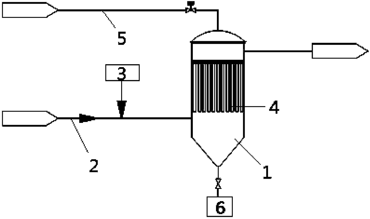
[0046] Embodiment 1 discloses a method for denitration and dust removal of flue gas, including the steps:

[0047] S10: adding a reducing agent to the flue gas to obtain a first flue gas, where the first flue gas includes dust, nitrogen oxides and a reducing agent;

[0048] S20: Pass the first flue gas through the catalytic filter assembly, the dust in the first flue gas is intercepted on the surface of the catalytic filter assembly to form a filter cake, and the reducing agent and nitrogen oxides in the first flue gas are denitrified in the catalytic filter assembly The reaction generates nitrogen and water to obtain clean flue gas;

[0049] S30: Expel the clean flue gas.

[0050] The method for denitration and dust removal of flue gas of the present invention obtains the first flue gas by adding a reducing agent to the flue gas, and makes the first flue gas pass through the catalytic filter assembly, thereby removing nitrogen oxides and dust in the first flue gas. The flue...

Embodiment 2

[0052] Compared with the first embodiment, the improvement of the second embodiment is that the method for denitration and dust removal of the flue gas in the second embodiment further includes step S40: collecting the dust filter cake on the surface of the catalytic filter assembly.

[0053] By regularly collecting dust filter cake on the surface of the catalytic filter assembly, the catalytic filter assembly can be effectively cleaned, thereby ensuring the catalytic filtering effect of the catalytic filter assembly to a certain extent.

Embodiment 3

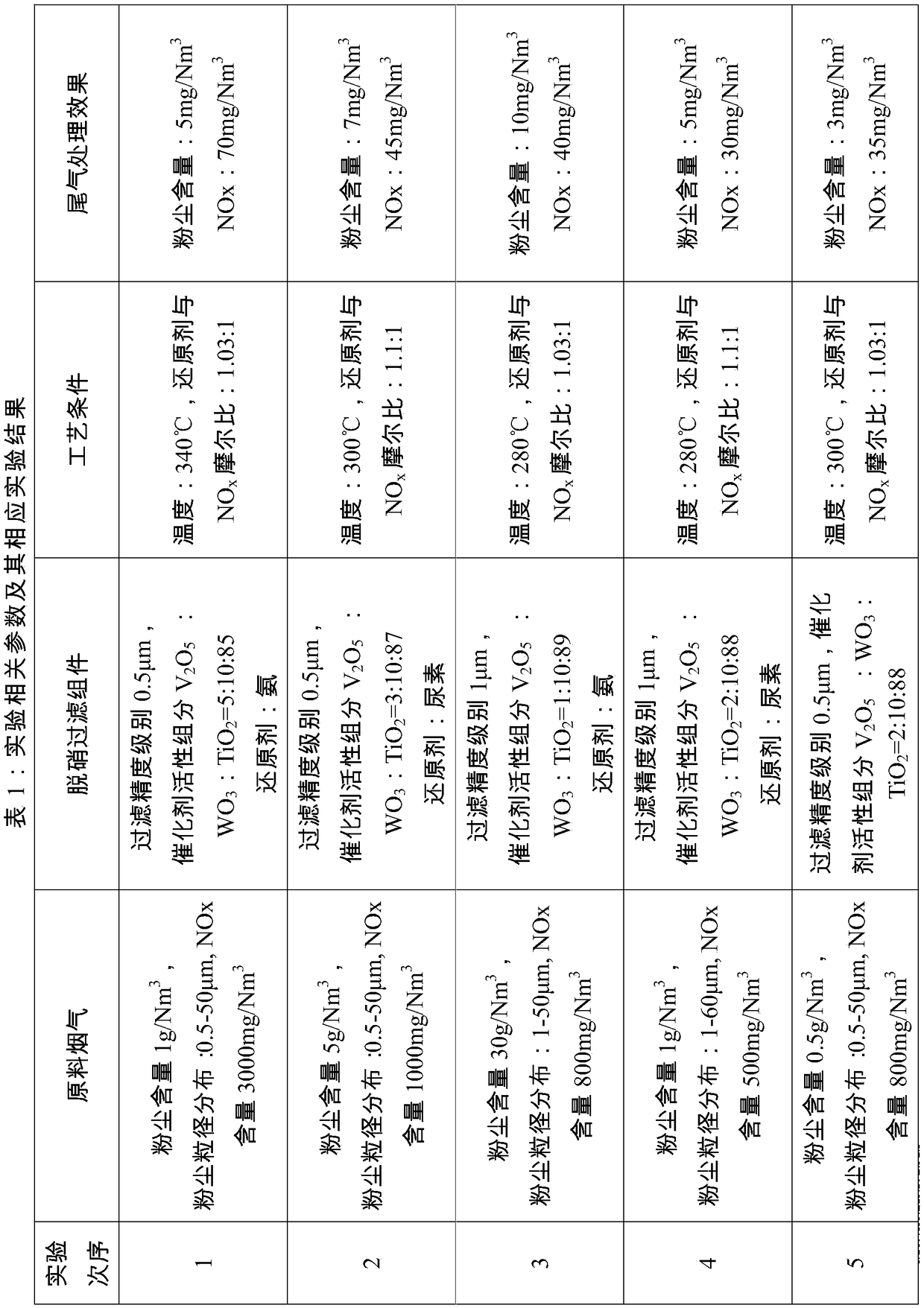
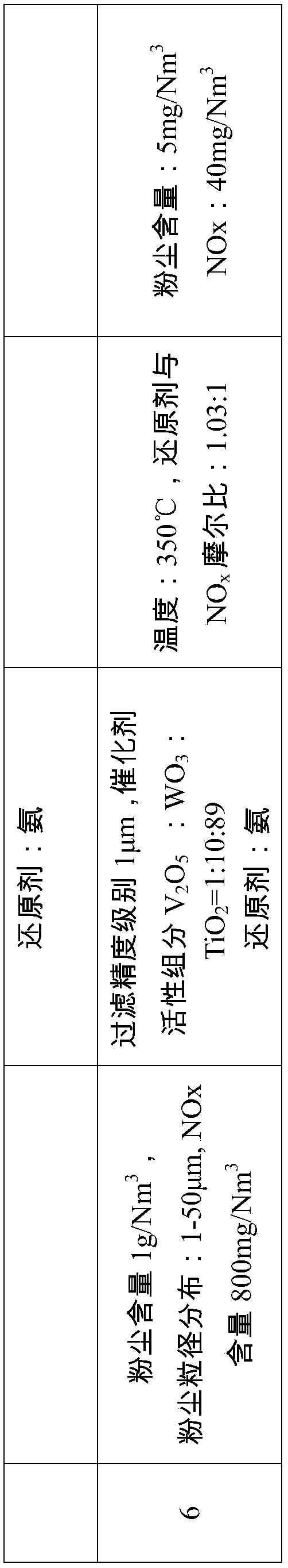
[0055] Compared with the first embodiment, the improvement of the third embodiment is that in the method for denitration and dust removal of the flue gas in the third embodiment, in step S10, the added reducing agent and the NO in the flue gas are added. X The molar ratio is 1:1~1.1:1. If the reducing agent and NO in the flue gas X If the ratio of the molar ratio is too small, the denitration reaction will not be completely complete, and if the ratio is too large, the ammonia escape will exceed the standard.

[0056] In step S20, when the reducing agent in the first flue gas undergoes a denitration reaction in the catalytic filter assembly, the reaction temperature is 250-380°C. If the reaction temperature of the denitration reaction is too high, the catalyst will be deactivated by sintering. If the reaction temperature is too low, the reaction rate will be too slow and the denitration efficiency will be low.

[0057] In this embodiment, the reducing agent is ammonia gas, li...


PUM


Abstract

The invention discloses a flue gas denitrification and dust removal method and system. The flue gas denitrification and dust removal method comprises the steps that firstly, a reducing agent is added into flue gas to obtain first flue gas, wherein the first flue gas comprises solid dust, nitrogen oxide and a reducing agent; secondly, the first flue gas is made to pass through a catalytic filter assembly, the dust in the first flue gas is stopped on the surface of the catalytic filter assembly to form a filter cake, the reducing agent and the nitrogen oxide in the first flue gas are subjected to a denitrification reaction in the catalytic filter assembly to generate nitrogen and water, and clean flue gas is obtained; thirdly, the clean flue gas is exhausted. According to the flue gas denitrification and dust removal method, the technology is simple, nitrogen oxide and solid dust in the flue gas can be effectively removed, the investment cost is low, the denitrification and dust removal efficiency is high, and the catalytic assembly is of a ceramic fiber sintering flexible structure and is resistant to corrosion, not prone to thermal shock and breakage and long in service life.

Description

technical field [0001] The invention relates to the technical field of flue gas purification methods and system design, in particular to a flue gas denitration and dust removal method and system. Background technique [0002] With the improvement of air pollution control and emission regulations, the pollution caused by particulate emissions and nitrogen oxides has attracted more and more attention, and the national emission control standards for particulate pollutants and nitrogen oxides in various industries have also been continuously improved. After being inhaled into the human body, particulate pollutants will directly enter the bronchi, interfere with gas exchange in the lungs, and cause diseases including asthma, bronchitis, and cardiovascular disease. x , mainly including NO, NO 2 , N 2 O, etc.) emissions into the atmosphere will not only form acid rain, but also cause chemical smog, which is harmful to human health. [0003] The flue gas treatment process current...

Claims


Application Information

Patent Timeline
Patent Type & Authority Patents(China)
IPC IPC(8): B01D53/76B01D53/78B01D53/86B01D53/56B01D46/54
CPCB01D46/54B01D53/76B01D53/78B01D53/8628B01D2251/2062B01D2251/2067B01D2255/20707B01D2255/20723B01D2255/20769B01D2255/20776
Inventor 马洪玺李雷张文军
Owner SHANGHAI LANKE PETROCHEM ENG & TECH
Why Eureka
Try Eureka