Numerical-control water hydraulic variable piston pump

A variable plunger, digital control technology, applied in the field of positive displacement pumps, can solve the problems of high transmission and control requirements, low water cylinder movement speed, application limitations of variable pump systems, etc., to solve the working medium pollution, improve life and reliability. , the effect of reducing the cost of use

Active Publication Date: 2016-06-15
无锡华芯晟光智控科技有限公司
View PDF6 Cites 4 Cited by
  • Summary
  • Abstract
  • Description
  • Claims
  • Application Information

AI Technical Summary

Problems solved by technology

Its principle is similar to the working principle of the valve-distribution plunger pump, but when the hydraulic cylinder is used instead of the plunger pump plunger as the suction and drainage working element, the working frequency of the reciprocating motion of the water cylinder is much lower than that of the column due to the low movement speed of the water cylinder. The working frequency of the plug pump leads to the prominent shortcomings of the pump such as large pressure pulsation, which greatly limits the application of the variable pump system in which the pressure signal is used as the feedback signal of the closed-loop control
[0006] With the wide application of water hydraulic transmission and control technology in food, fire protection, iron and steel, metallurgy, coal mine, chemical industry, injection molding, marine engineering, medicine, food, packaging, environmental protection, water treatment and other fields, general water hydraulic quantitative pump and water hydraulic control The valve control method is far from meeting the increasingly high transmission and control requirements in terms of power adjustment, energy saving, efficiency improvement, control accuracy improvement, and digital control.

Method used


Image

  • Numerical-control water hydraulic variable piston pump
  • Numerical-control water hydraulic variable piston pump
  • Numerical-control water hydraulic variable piston pump

Examples


Embodiment Construction

[0020] The present invention will be further described below in conjunction with the accompanying drawings and specific embodiments.

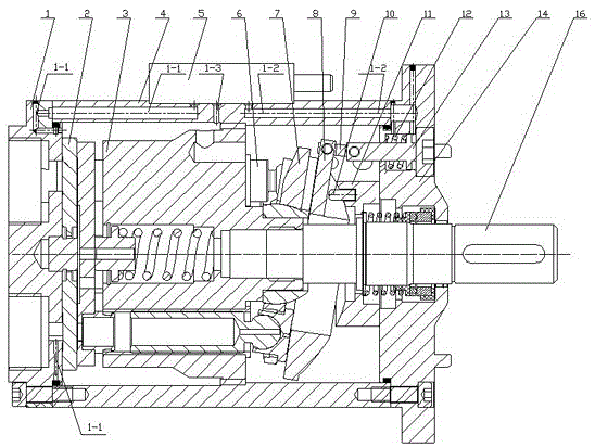
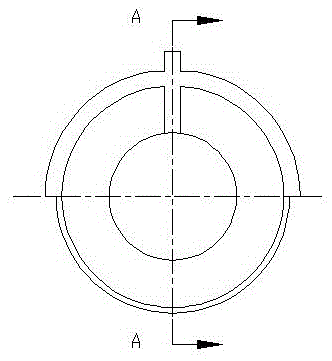
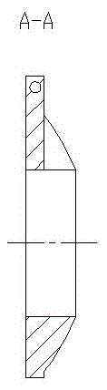
[0021] as attached figure 1 , 2 , 3, and 4, the present invention includes a rear end cover 1, a distribution plate 2, a rotating cylinder assembly 3, a housing 4, a water-hydraulic electro-hydraulic proportional valve 5, an odd number of plunger shoe assemblies 6, a return plate 7, Variable swash plate 8, connecting rod 9, swash plate bushing 11, variable spring 12, variable piston 13, front end cover 14 and shaft 16, A high-pressure water channel 1-1 and B high-pressure water channel 1 are respectively arranged on the housing 4 -2 and C high-pressure water channels 1-3, the rear end cover 1 and the front end cover 14 are respectively fixedly installed on both ends of the housing 4, the distribution plate 2 is installed on the rear end cover 1 and is located in the housing 4, and the return plate One side of 7 is installed on the front end c...


PUM


Abstract

The invention provides a numerical-control water hydraulic variable piston pump. The numerical-control water hydraulic variable piston pump comprises a rear end cover (1), a valve plate (2), a rotary cylinder body assembly (3), a shell (4), a water hydraulic electro-hydraulic proportional valve (5), piston shoe assemblies (6), a set plate (7), a variable swash plate (8), a connecting rod (9), a swash plate lining (11), a variable spring (12), a variable piston (13), a front end cover (14) and a shaft (16), wherein the number of the piston shoe assemblies (6) is an odd number. The swash plate angle change of the pump is controlled through the interaction of the water hydraulic electro-hydraulic proportional valve, the variable piston and the variable swash plate, and displacement control of the water hydraulic pump is achieved. According to the numerical-control water hydraulic variable piston pump, a pin is matched with a groove in the spherical surface of the variable swash plate so that the lateral force generated in the process that rotating friction of the piston shoe assemblies drive the variable swash plate to rotate can be effectively reduced or eliminated, and the lateral impact on a variable mechanism composed of the connecting rod and the variable piston can be reduced, so that the service life of the variable mechanism is greatly prolonged, and the reliability of the variable mechanism is greatly improved.

Description

technical field [0001] The invention relates to the technical field of displacement pumps, in particular to a digitally controlled water hydraulic variable displacement plunger pump. Background technique [0002] In recent years, breakthroughs have been made in water hydraulic transmission and control technology that directly uses water (filtered natural water, including seawater and fresh water) instead of mineral oil as the working medium, and in a wide range of engineering applications, compared with traditional oil Hydraulic transmission has proved to have outstanding advantages such as environmental protection, cleanliness, high efficiency, convenient use and maintenance, and low operating cost. Water hydraulic transmission and control technology has been widely used in high-pressure water atomization, seawater desalination, high-pressure water cleaning, stage drive and control, submersible buoyancy adjustment system, marine engineering and other transmission and contro...

Claims


Application Information

Patent Timeline
Patent Type & Authority Applications(China)
IPC IPC(8): F04B1/22F04B1/32F04B53/00
CPCF04B1/2078F04B1/22F04B1/324
Inventor 郭志恒
Owner 无锡华芯晟光智控科技有限公司
Why Eureka
Try Eureka