
Surface modification method for SnO<2>-based photo-anode

A surface modification, photoanode technology, applied in photovoltaic power generation, photosensitive equipment, capacitor electrodes, etc., can solve the problems of strong corrosion, expensive equipment, strong irritation of the upper respiratory tract mucosa, etc., to achieve the effect of improving performance

Inactive Publication Date: 2016-05-25
XIANGTAN UNIV
View PDF2 Cites 2 Cited by
  • Summary
  • Abstract
  • Description
  • Claims
  • Application Information

AI Technical Summary

Problems solved by technology

However TiCl 4 It is a highly toxic liquid that produces toxic and corrosive (hydrogen chloride) fumes in the air or in contact with water, which are highly corrosive and irritating
It is not easy to protect during use, and it is easy to cause physical harm to experimental or production personnel-inhalation of the fume will cause strong irritation of the upper respiratory tract mucosa (mild poisoning has symptoms of asthmatic bronchitis; severe cases have dyspnea, respiratory pulse Accelerate, body temperature rise, cough, expectoration, etc., can develop into pulmonary edema)
In addition to releasing corrosive hydrogen chloride, TiCl 4 Very easy to hydrolyze, even dissolve TiCl in ice-water mixture 4 Also often due to TiCl 4 rapid hydrolysis without obtaining a clear solution
In addition, TiCl 4 Titanium oxides and oxychlorides will also be generated when exposed to water or in humid air, which will stick to the syringe used, which also increases the risk of configuring TiCl. 4 solution difficulties
And its aqueous solution because TiCl 4 The rapid hydrolysis cannot be stored for a long time, and it can only be prepared and used now
[0004] Atomic layer deposition (ALD) technology can also be very good on nano-SnO 2 An effective passivation layer is prepared on the surface of the structure, but the atomic layer deposition (ALD) equipment is expensive and the cost of preparation is high

Method used


Image

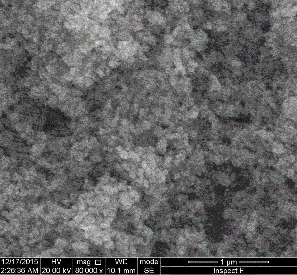
  • Surface modification method for SnO&lt;2&gt;-based photo-anode
  • Surface modification method for SnO&lt;2&gt;-based photo-anode
  • Surface modification method for SnO&lt;2&gt;-based photo-anode

Examples


Embodiment 1

[0017] (1) SnO 2 The porous film is immersed in a mixed solution of concentrated ammonia water (25% by mass fraction) and aqueous hydrogen peroxide solution (30% by mass) with a volume ratio of 1:1. After 5 minutes, it is taken out and rinsed with deionized water to obtain a hydrophilic surface. treated SnO 2 porous film.

[0018] (2)CrO x Preparation of the modification layer

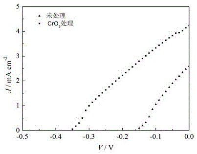
[0019] a) 1gCrO 3 Dissolve in 100ml secondary deionized water to obtain solution a; b) configure 0.2mol / L aqueous solution b of acetic acid; c) hydrophilize the SnO 2 Soak the porous film in solution a, take it out after a certain period of time and soak it in deionized water or rinse it with deionized water, then soak it in solution b for a period of time, take it out and soak it in deionized water or rinse it with deionized water; repeat step c) Three times, calcined at 550°C to obtain CrO x Surface modified SnO 2 Photoanode.

[0020] (3) CdS quantum dots were deposited on the photoanode by t...

Embodiment 2

[0022] (1) SnO 2 The porous film is immersed in a mixed solution of concentrated ammonia water (25% by mass fraction) and aqueous hydrogen peroxide solution (30% by mass) with a volume ratio of 1:1. After 5 minutes, it is taken out and rinsed with deionized water to obtain a hydrophilic surface. treated SnO 2 porous film.

[0023] (2)CrO x Preparation of the modification layer

[0024] a) Add 2gNa 2 Cr 2 o 7 Dissolve in 100ml secondary deionized water to obtain solution a; b) configure 0.1mol / L HCl aqueous solution b; c) hydrophilize the SnO 2 Soak the porous film in solution a, take it out after a certain period of time and soak it in deionized water or rinse it with deionized water, then soak it in solution b for a period of time, take it out and soak it in deionized water or rinse it with deionized water; repeat step c) Twice, calcined at 500°C for 30min to obtain CrO x Surface modified SnO 2 Photoanode.

[0025] (3) CdS quantum dots were deposited on the photoano...

Embodiment 3

[0027] (1) SnO 2 The porous film is immersed in a mixed solution of concentrated ammonia water (25% by mass fraction) and aqueous hydrogen peroxide solution (30% by mass) with a volume ratio of 1:1. After 5 minutes, it is taken out and rinsed with deionized water to obtain a hydrophilic surface. treated SnO 2 porous film.

[0028] (2)CrO x Preparation of the modification layer

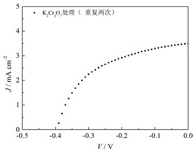
[0029] a) Add 4gK 2 Cr 2 o 7 Dissolve in 100ml secondary deionized water to obtain solution a; b) configure 0.2mol / L HCl aqueous solution b; c) hydrophilize the SnO 2 Soak the porous film in solution a, take it out after 2 minutes and soak it in deionized water or rinse it with deionized water, then soak it in solution b for a period of time, take it out and soak it in deionized water or rinse it with deionized water; repeat step c) 4 times, calcined at 500°C for 30min to obtain CrO x Surface modified SnO 2 Photoanode.

[0030] (3) CdS quantum dots were deposited on the photoanode by the cont...


PUM


Abstract

The invention discloses a surface modification method for an SnO<2>-based photo-anode, and belongs to the field of photoelectrochemistry. The surface modification method comprises the following implementation steps: (1) dissolving soluble chromic acid or chromate containing high-valent chromium into water to prepare a chromic acid or chromate solution a containing the high-valent chromium; (2) preparing a water solution b of a non-oxidizing acid with certain concentration; (3) soaking an SnO<2> mesoporous thin film of which the surface is subjected to hydrophilizing treatment into the solution a for a certain period of time, taking out and soaking the SnO<2> mesoporous thin film into deionized water or washing the SnO<2> mesoporous thin film with the deionized water, soaking the SnO<2> mesoporous thin film into the solution b for a certain period of time, taking out and soaking the SnO<2> mesoporous thin film into the deionized water or washing the SnO<2> mesoporous thin film with the deionized water, and drying the SnO<2> mesoporous thin film at a certain temperature; and (4) repeating the step (3) for a plurality of times, drying and burning the SnO<2> mesoporous thin film to obtain the SnO<2>-based photo-anode subjected to CrO<x> surface modification. The effect improvement of the SnO<2>-based photo-anode prepared by the method disclosed by the invention is obvious; and the method is simple to operate and easy to implement.

Description

technical field [0001] The present invention relates to a kind of SnO 2 The surface modification method of the base photoanode is mainly applied in photoelectrochemical related fields such as sensitized solar cells, photolysis of water, and photofuel cells. Background technique [0002] The current environmental pollution problem is serious, and the development and utilization of new energy is imminent. In recent years, solar energy has attracted much attention as a clean energy. Photoelectrochemical devices such as sensitized solar cells, photolytic water splitting, and photofuel cells are one of the important ways for the potential utilization of solar energy in the future. SnO 2 As a wide-bandgap semiconductor with cheap, non-toxic, abundant raw materials, stable chemical properties and high carrier mobility, it has become a matrix material for photoelectrochemical devices with great potential. But nano SnO 2 The surface state density of the structure is high, which ...

Claims


Application Information

Patent Timeline
Patent Type & Authority Applications(China)
IPC IPC(8): H01G9/04H01G9/20
CPCH01G9/04H01G9/2027Y02E10/542
Inventor 王金斌田自然钟向丽肖君林
Owner XIANGTAN UNIV
Learn More