Forming method of non-alloy ohmic contact of GaN HEMT device

A non-ohmic contact and ohmic contact technology, used in semiconductor/solid-state device manufacturing, semiconductor devices, electrical components, etc., can solve the problems of GaN device leakage current, device power degradation, GaN lattice damage, etc. The effect of reducing roughness and improving reliability

Inactive Publication Date: 2016-05-04
CHENGDU HIWAFER SEMICON CO LTD
View PDF3 Cites 5 Cited by
  • Summary
  • Abstract
  • Description
  • Claims
  • Application Information

AI Technical Summary

Problems solved by technology

[0004] At present, due to the high work function of the GaN cap layer of conventional GaN devices, if a good ohmic contact cannot be achieved, the power of the device will be severely degraded. In order to solve this problem, the industry usually uses high-temperature annealing to achieve ohmic contact.
However, the temperature of the high temperature annealing method reaches 850 degrees. Such a high temperature will cause damage to the GaN lattice, causing leakage and current collapse of the GaN device, and affecting the reliability of the GaN device.
Therefore, the ohmic contact implementation of conventional GaN devices is the main bottleneck hindering the performance improvement and practical application of GaN devices.

Method used


Image

  • Forming method of non-alloy ohmic contact of GaN HEMT device
  • Forming method of non-alloy ohmic contact of GaN HEMT device
  • Forming method of non-alloy ohmic contact of GaN HEMT device

Examples


Embodiment Construction

[0020] The following will clearly and completely describe the technical solutions in the embodiments of the present invention with reference to the accompanying drawings in the embodiments of the present invention. Obviously, the described embodiments are only some, not all, embodiments of the present invention. Based on the embodiments of the present invention, all other embodiments obtained by persons of ordinary skill in the art without making creative efforts belong to the protection scope of the present invention.

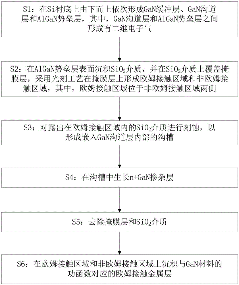
[0021] see figure 1 , is a schematic diagram of a method for fabricating a non-alloy ohmic contact of a GaNHEMT device according to an embodiment of the present invention. The fabrication method of the GaNHEMT device non-alloy ohmic contact of the present embodiment comprises the following steps:

[0022] S1: A GaN buffer layer, a GaN channel layer and an AlGaN barrier layer are sequentially formed on a Si substrate from bottom to top, wherein a two-dimension...


PUM


Abstract

The invention provides a forming method of non-alloy ohmic contact of a GaN HEMT device. The method comprises the steps of: forming a GaN buffer layer, a GaN channel layer and an AlGaN barrier layer successively on a Si substrate; deposing a SiO2 medium on the surface of the AlGaN barrier layer, covering the SiO2 medium with a mask layer, and using a photoetching process to form ohmic contact areas and a non-ohmic-contact area on the mask layer, wherein the ohmic contact areas are arranged at two sides of the non-ohmic-contact area; carrying out etching on the SiO2 medium exposed in the ohmic contact areas so as to form a channel embedded in the GaN channel layer; growing a n+GaN doped layer in the channel; removing the mask layer and the SiO2 medium; and deposing an ohmic contact metal layer corresponding to a GaN material on the ohmic contact areas and the non-ohmic-contact area. By adopting the method provided by the invention, damages of high-temperature annealing to GaN crystal lattices are avoided.

Description

technical field [0001] The invention relates to the technical field of semiconductor devices, in particular to a method for manufacturing non-alloy ohmic contacts of GaNHEMT devices. Background technique [0002] After decades of development of silicon-based chips, the size of Si-based CMOS devices has been continuously reduced, but its frequency performance has been continuously improved. When the feature size reaches 25nm, its f T Up to 490GHz. However, the Johnson figure of merit of Si material is only 0.5THzV, and the reduction in size makes the breakdown voltage of Si-based CMOS devices far less than 1V, which greatly limits the application of silicon-based chips in the ultra-high-speed digital field. [0003] In recent years, people are constantly looking for substitutes for Si materials. Since the wide-bandgap semiconductor Gallium Nitride (GaN) material has an ultra-high Johnson figure of merit (up to 5THzV), when the device channel size reaches the order of 10nm, i...

Claims


Application Information

Patent Timeline
Patent Type & Authority Applications(China)
IPC IPC(8): H01L29/06H01L29/45H01L21/335
CPCH01L29/66462H01L29/0692H01L29/454
Inventor 黎明陈汝钦
Owner CHENGDU HIWAFER SEMICON CO LTD
Why Eureka
Try Eureka