
A dry etching device and method

A technology of dry etching device and etching chamber, which is applied in the manufacture of discharge tubes, electrical components, semiconductors/solid-state devices, etc., and can solve the problems of standing waves on electrode surfaces, inability to etch uniformly over a large area, and uneven etching rates, etc. problems, to achieve the effect of improving uniformity, increasing etching speed, and uniform etching

Active Publication Date: 2018-06-29
BOE TECH GRP CO LTD +1
View PDF11 Cites 0 Cited by
  • Summary
  • Abstract
  • Description
  • Claims
  • Application Information

AI Technical Summary

Problems solved by technology

However, increasing the frequency of the excitation source will cause problems such as standing waves on the surface of the electrode, resulting in uneven etching rates and inability to uniformly etch large areas.

Method used


Image

  • A dry etching device and method
  • A dry etching device and method
  • A dry etching device and method

Examples


Embodiment Construction

[0028] In order to make the technical problems, technical solutions and advantages to be solved by the present invention clearer, the following will describe in detail with reference to the drawings and specific embodiments.

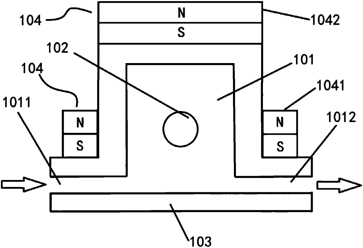
[0029] The present invention firstly provides a dry etching device, such as figure 1 As shown, it includes a vacuum etching chamber 101, a coaxial circular waveguide 102, a carrier for carrying a substrate to be etched, and a coaxial microwave source connected to the coaxial circular waveguide; wherein:

[0030] The coaxial circular waveguide 102 is arranged inside the vacuum etching chamber 101, and is used to transmit electromagnetic waves generated by the coaxial microwave source to excite plasma, so that the plasma etches the to-be-treated area under the coaxial circular waveguide 102. Etch the substrate.

[0031] It can be seen from the above that the dry etching device provided by the present invention uses a coaxial microwave source to generate e...


PUM


Abstract

The invention provides a dry etching device and a dry etching method. The dry etching device comprises a vacuum etching cavity, a coaxial circular waveguide, a bearing piece used for bearing a substrate to be etched, and a coaxial microwave source connected with the coaxial circular waveguide, wherein the coaxial circular waveguide is arranged inside the vacuum etching cavity and is used for transmitting electromagnetic waves generated by the coaxial microwave source so as to excite plasma, and thus the plasma etches the substrate to be etched below the coaxial circular waveguide. The dry etching method adopts the dry etching device provided by any embodiment of the invention for etching, and comprises the step of adjusting etching time of the substrate to be etched below the coaxial circular waveguide, so that the etching depth of the substrate to be etched reaches a set value.

Description

technical field [0001] The invention relates to the technical field of production and manufacturing, in particular to a dry etching device and method. Background technique [0002] Dry etching is a technique that uses plasma to etch thin films. When the gas exists in the form of plasma, it has two characteristics: on the one hand, the chemical activity of these gases in the plasma is much stronger than that under normal conditions. React with the material to achieve the purpose of etching and removal. In the prior art, the plasma excitation method used for high-rate dry etching is mainly ICCP (Impressed Current Cathodic Protection, Impressed Current Cathodic Protection). If you want to further increase the etching rate, generally speaking, you can increase the frequency of the plasma excitation source. A higher plasma cut-off density is obtained to achieve the purpose of increasing the etching rate. However, increasing the frequency of the excitation source will cause pro...

Claims


Application Information

Patent Timeline
Patent Type & Authority Patents(China)
IPC IPC(8): H01J37/32H01L21/3065
CPCH01J37/32H01J37/32192H01J37/32229H01L21/3065
Inventor 魏钰袁广才王东方周斌
Owner BOE TECH GRP CO LTD
Learn More