Portable bi-directional constant current source module

A constant current source module, portable technology, applied in the field of electronics, can solve the problems of large impact, drop, low efficiency, etc.

Inactive Publication Date: 2016-04-27
JILIN UNIV
View PDF5 Cites 17 Cited by
  • Summary
  • Abstract
  • Description
  • Claims
  • Application Information

AI Technical Summary

Problems solved by technology

Among these schemes, the first scheme is greatly affected by the device itself and has limited improvement in stability; the second scheme can effectively reduce the impact of changes in load resistance due to a large resistor connected in series in the load circuit. The influence of the output current, but due to the existence of the large resistance of the load circuit, the output current is very small, generally only in the milliampere level, and most of the power is dropped on the large resistance, which also makes the efficiency extremely low; the third scheme Due to the automatic adjustment function of the negative feedback network itself, the output current can be automatically stabilized without being affected by load changes, so it is currently the most effective way to improve current stability. However, in the currently disclosed technologies, generally Adopting a single linear feedback network, the biggest disadvantage of this scheme is that once the feedback network fails, the system will be in an open-loop working state, the output current will increase sharply, and it is easy to damage the load and the circuit itself. Another disadvantage is the use of The occasion is limited, and it can only be applied to the occasion where the load responds linearly to the current. In some specific occasions, if the load responds to the current with a delay or lead, this constant current source based on a single linear feedback network will lose automatic stabilization capability
In addition, the current common constant current source devices are all desktop instruments, which are bulky, heavy, and not easy for system integration.

Method used


Image

  • Portable bi-directional constant current source module
  • Portable bi-directional constant current source module
  • Portable bi-directional constant current source module

Examples


Embodiment 1

[0040] Embodiment 1 Overall structure of the present invention

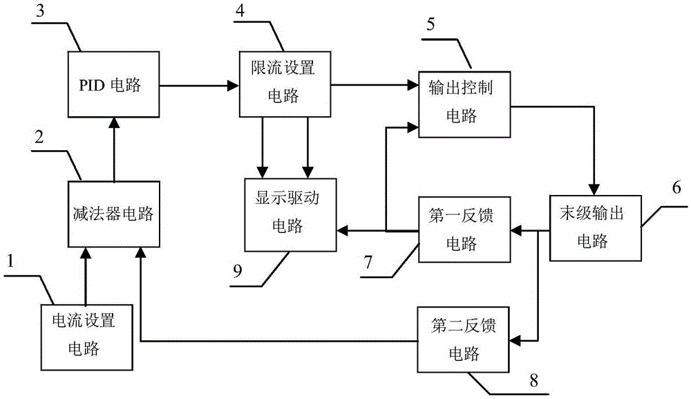
[0041] to combine figure 1 The overall working principle of a bidirectional constant current source circuit of the present invention is described. A reference voltage is set through the current setting circuit 1, and the second feedback circuit 8 samples the output current and converts it into a corresponding voltage. The above two voltages are differenced in the subtractor circuit 2, and the difference is sent to the PID circuit 3 for PID Operation, the result of the operation is sent to the current limit setting circuit 4, if the result of the operation is within the current limit value range set by the current limit setting circuit 4, then the calculation result is directly output, if the result of the operation exceeds the current limit setting circuit 4 current limit value range, then output the current limit value, the output value of the current limit setting circuit 4 is sent to the control input termina...

Embodiment 2

[0042] Example 2 front panel

[0043] The structure of front panel 10 of the present invention is as Figure 12As shown, the structure includes: 9-pin D-shaped interface 101, upper limit adjustment 102, lower limit adjustment 103 and output adjustment 104; see Figure 13 , pin 1 and pin 5 of the 9-pin D-shaped interface 101 are grounded, pin 6 is connected to the power supply VCC, pin 2 is connected to the power supply VEE, pin 7 and pin 3 are respectively connected to the port CURRENT+ and port CURRENT- of the final output circuit 6, Pin 8, pin 4, and pin 9 are respectively connected to the port CURRENT_DIS, port LIMIT_L_DIS, and port LIMIT_H_DIS of the display drive circuit 9; the upper limit adjustment 102 and the lower limit adjustment 103 are respectively the potentiometer W2 and the potentiometer in the current limiting setting circuit 4 The adjustment screw of W3; the output adjustment 104 is the adjustment screw of the potentiometer W1 in the current setting circuit 1...

Embodiment 3

[0045] Embodiment 3 current setting circuit

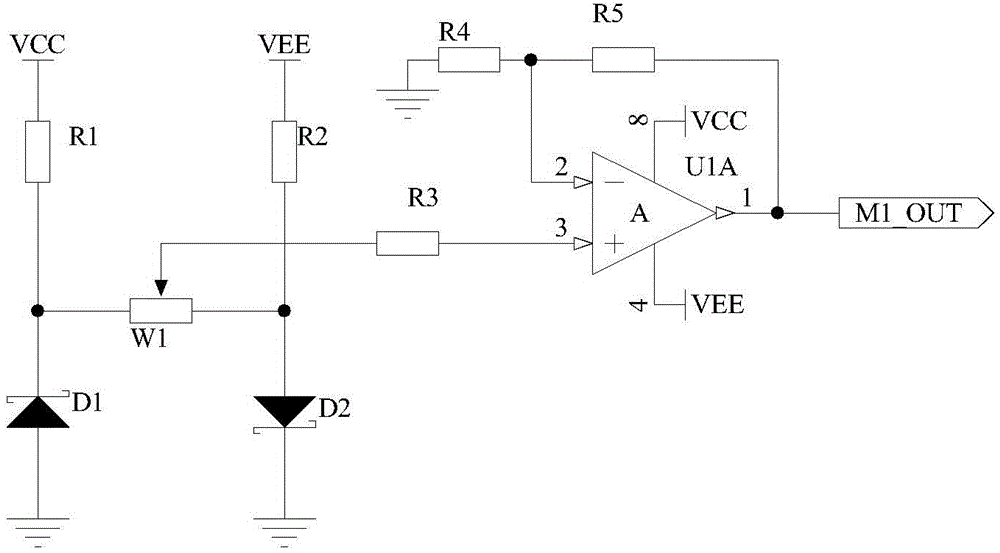
[0046] The principle circuit of the current setting circuit 1 of the present invention is as figure 2 As shown, one end of the resistor R1 is connected to the power supply VCC, the other end is connected to the cathode of the Zener diode D1 and one end of the potentiometer W1, the anode of the Zener diode D1 is grounded, one end of the resistor R2 is connected to the power supply VEE, and the other end is connected to the Zener diode D2 The anode of the potentiometer W1 and the other end of the potentiometer W1, the cathode of the Zener diode D2 is grounded, the slide wire of the potentiometer W1 is connected to one end of the resistor R3, the other end of the resistor R3 is connected to the non-inverting input terminal of the operational amplifier U1A, and the reverse terminal of the operational amplifier U1A The phase input terminal is connected to one end of the resistor R4 and one end of the resistor R5, the other end of the r...


PUM


Abstract

A portable bi-directional constant current source module provided by the invention belongs to the technical field of electronic techniques. The portable bi-directional constant current source module structurally comprises a current setting circuit (1), an output control circuit (5), a final output circuit (6) and a first feedback circuit (7), and is characterized by also structurally comprising a subtracter circuit (2), a PID circuit (3), a current-limiting setting circuit (4), a second feedback circuit (8), a display drive circuit (9) and a front panel (10). The portable design is adopted, a 9-pin D-shaped interface is used as an input / output interface, the structure is compact, system integration is easy, the circuit part adopts a double negative feedback structure, so that the characteristics of stable and high output current, high safety, wide usage occasions and the like, and output current two-way regulation also can be realized.

Description

technical field [0001] The present invention belongs to the technical field of electronic technology. In particular, it relates to a portable high-stability bidirectional constant current source module. Background technique [0002] The constant current source has important applications in many occasions such as fiber optic communication, LED lighting, laser driving, etc. In some occasions, such as laser driving, the output current stability of the constant current source is very important, and the instability of the output current will cause problems. Affect the life of the laser and the output optical power. The commonly used measures to improve the current stability are: 1. Use the nonlinear magnetization principle of the magnetic saturable reactor to improve the stability; 2. Connect a large resistance in series in the load loop (relative to the load resistance); 3. Realize the current through a negative feedback network Automatic stabilization. Among these schemes, t...

Claims


Application Information

Patent Timeline
Patent Type & Authority Applications(China)
IPC IPC(8): G05F1/46
CPCG05F1/461
Inventor 汝玉星吴戈单江东高博田小建刘大恺梁雪马春阳张大朋安明李尚
Owner JILIN UNIV
Why Eureka
Try Eureka