Method of forming conductive films with micro-wires

一种微丝、导电组合物的技术,应用在电路、薄料处理、电气元件等方向,能够解决微丝突出微通道、断裂等问题,达到改善电导率和透明度、优异光学性质、改善微丝电导率和基底透明度的效果

Inactive Publication Date: 2016-04-20
EASTMAN KODAK CO
View PDF14 Cites 5 Cited by
  • Summary
  • Abstract
  • Description
  • Claims
  • Application Information

AI Technical Summary

Problems solved by technology

Conversely, weak filament cohesion can lead to protruding microchannels and fracture of filaments

Method used


Image

  • Method of forming conductive films with micro-wires
  • Method of forming conductive films with micro-wires
  • Method of forming conductive films with micro-wires

Examples


Embodiment 1

[0126] Invention embodiment 1: Formation of conductive films containing microfilaments

[0127] A polyethylene terephthalate film having a thickness of about 125 μm was surface-treated with a latex containing polyvinylidene chloride to form an adhesion-promoting subbing layer. 34.0 g of Epon resin SU-8, 6.0 g of Coatosil MP-200, 4.8 g of triarylsulfonium hexafluorophosphate (mixed, 50% dispersed in propylene carbonate) and 55.2 g of methyl ethyl ketone A coating solution composed of (MEK) was applied as a photocurable composition on the base layer and dried to form a photocurable layer having a nominal dry thickness of about 12 μm. The photocurable surface of the resulting dry film was then covered with a protective sheet approximately 25.4 μm thick, one surface of which was treated with a silicone release coating. The protective foil can be easily separated from the photocurable layer.

[0128]At 90° C., the photocurable layer on the substrate was continuously extruded at...


PUM

PropertyMeasurementUnit
hazeaaaaaaaaaa
transparencyaaaaaaaaaa

Abstract

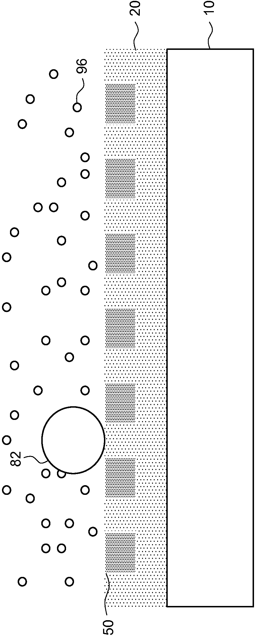
A pattern of conductive micro-wires as in a conductive pattern can be prepared using photo-lithography, or imprint technology. A photocurable composition is cured to form a pattern of photocured micro-channels. A conductive composition comprising metal nano-particles is added to the photocured micro-channels and excess conductive composition outside the photocured micro-channels is removed. The conductive composition in the photocured micro-channels is then dried at a temperature of less than 60 DEG C. The dried conductive composition in the photocured micro-channels is treated with hydrogen chloride vapor to form conductive micro-wires in the photocured micro-channels at a temperature of less than 60 DEG C. The outer surface of the conductive micro-wires is then polished in the presence of water, to form a micro-wire pattern.

Description

field of invention [0001] The present invention relates to a method for forming a pattern of fibrils on a substrate in an electrically conductive article. More specifically, the present invention relates to methods for forming conductive articles (films) comprising fine line patterns of conductive microfilaments provided using photo-imprintlithography. Background of the invention [0002] Photoimprinting techniques have been proposed as a method for forming micron and submicron sized features on substrates. In such techniques, a pattern is formed by pressing an imprinting stamp or mold having a preformed pattern on its surface against a substrate having a layer (receiving layer) that can be imprinted. Both thermoplastic resins and photocurable resins can be used as the receiving layer. The thermoplastic resin may be heated above its softening point prior to embossing and then cooled to a lower temperature that causes the graphic to be fixed to the surface of the receiving ...

Claims


Application Information

Patent Timeline
Patent Type & Authority Applications(China)
IPC IPC(8): G03F7/00
CPCG03F7/0002G03F7/038Y10T428/24917H01B1/02H01B13/30H01B13/0013H01B13/003H01B13/0036
Inventor Y.王J.A.勒本斯M.L.赖特
Owner EASTMAN KODAK CO
Why Eureka
Try Eureka