
Polysilicon etching method

A polysilicon and polysilicon layer technology, applied in semiconductor devices and other directions, can solve problems such as rough edges of polysilicon lines, and achieve the effects of solving rough edges, reducing deposition thickness, and improving etching resistance.

Inactive Publication Date: 2016-04-06
SHANGHAI HUALI MICROELECTRONICS CORP
View PDF8 Cites 1 Cited by
  • Summary
  • Abstract
  • Description
  • Claims
  • Application Information

AI Technical Summary

Problems solved by technology

[0008] In view of the above existing problems, the present invention discloses a polysilicon etching method to overcome the problem in the prior art that the rough edges of polysilicon lines are caused by the roughness of the photoresist pattern continuously passing down during the etching process

Method used


Image

  • Polysilicon etching method
  • Polysilicon etching method
  • Polysilicon etching method

Examples


Embodiment Construction

[0029] The present invention will be further described below in conjunction with the accompanying drawings and specific embodiments, but not as a limitation of the present invention.

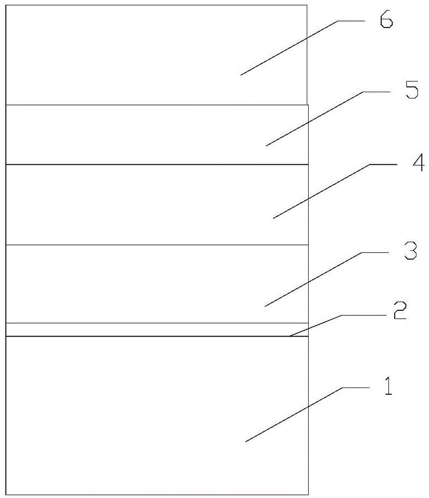
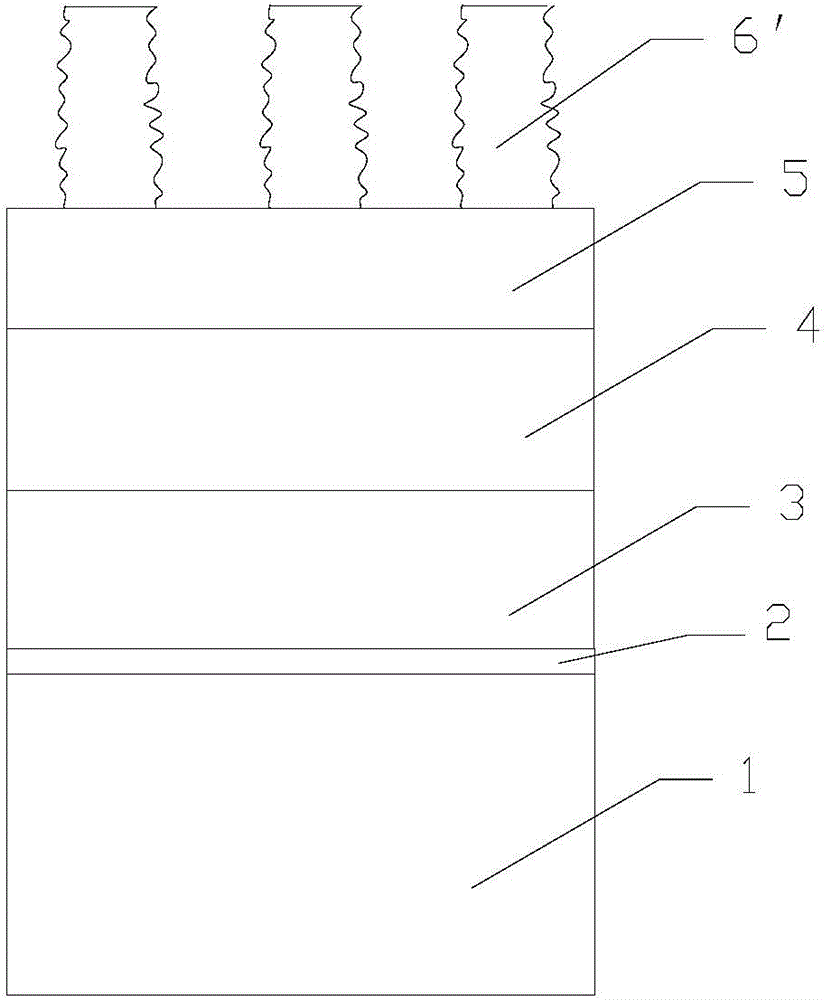
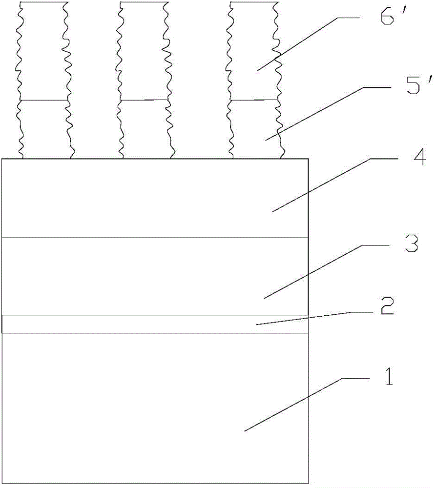
[0030] Figure 1-7 It is a schematic diagram of the flow structure of the polysilicon etching method in the embodiment of the present invention; Figure 1-7 Shown:

[0031] This embodiment relates to a polysilicon etching method, comprising the following steps:

[0032] In step S1, a semiconductor substrate 1 is provided, which is a silicon substrate, and then a gate oxide layer 2, a polysilicon layer 3, a hard mask layer 4, and a BARC layer (anti-reflective coating layer) are formed sequentially from bottom to top. layer) 5 and photoresist layer 6 cover the upper surface of the semiconductor substrate 1, in this step, the method of depositing the polysilicon layer 3 can be chemical vapor deposition or furnace tube deposition, because the gate oxide layer 2, polysilicon layer 3. The process of ...


PUM

PropertyMeasurementUnit
Thicknessaaaaaaaaaa

Abstract

The invention provides a polysilicon etching method. Through processing a photoresist which is formed after photoresist patterning and a residual bottom antireflective coating (BARC) layer after etching by means of plasma which has advantages of high frequency, low pressure and zero bias voltage and comprises HBr, edges of the photoresist and the residual BARC layer are smoothed. Then, the residual photoresist and the BARC layer after processing by the plasma which comprises the HBr is used as a mask for etching a hard mask layer and a polysilicon layer on the upper surface of the semiconductor substrate, thereby settling a problem of rough line edge of the polysilicon. Furthermore, the surface of processed photoresist absorbs the plasma which comprises HBr and Cl2, and the property of the photoresist changes. Etching resistance is improved, and selectivity ratio to the hard mask is improved, thereby reducing deposition thickness of the photoresist layer, and furthermore reducing time and raw material consumed in depositing the photoresist. Namely the polysilicon etching method has advantages of reducing production cost, improving production efficiency and saving resource.

Description

technical field [0001] The invention relates to the technical field of semiconductor manufacturing, in particular to a polysilicon etching method. Background technique [0002] In the semiconductor manufacturing process, it is usually found that the lines of polysilicon are rough after polysilicon etching. Sometimes the difference between the critical dimensions of two polysilicon lines can reach 8-11nm. The reason for the rough lines of polysilicon is mainly due to the lines of photoresist patterns. Roughness is caused by continuous downward transmission during the etching process. There are two main reasons for the rough lines of the photoresist pattern: one is that different patterns under the photoresist will affect the reflected light from the reflective layer under the photoresist, and the reflected light will be reflected in the photoresist that does not need to be exposed. The reflection cut is formed, resulting in rough lines; the second is the direct interference ...

Claims


Application Information

Patent Timeline
IPC IPC(8): H01L21/28
Inventor 高慧慧秦伟杨渝书李程
Owner SHANGHAI HUALI MICROELECTRONICS CORP
Learn More