
Reflective NEA GaN nanowire array photoelectric negative electrode and manufacturing method therefor

A nanowire array and photocathode technology, applied in the fields of photoemission cathode, cold cathode manufacturing, electrode system manufacturing, etc., can solve the problems of low repeatability, expensive equipment, high emissivity of thin film materials, etc., to improve quantum efficiency, The loss of energy is small, and the effect of overcoming the conflicting relationship

Inactive Publication Date: 2016-03-23
NANJING UNIV OF SCI & TECH
View PDF5 Cites 15 Cited by
  • Summary
  • Abstract
  • Description
  • Claims
  • Application Information

AI Technical Summary

Problems solved by technology

Metal-organic chemical vapor deposition method has the disadvantages of expensive equipment, and the reaction raw materials are metal-organic compounds that are not easy to preserve, so the repeatability is not high; while the dry etching method is simple in equipment, low in cost and easy to implement, but because its reaction mechanism is through Corrosion of semiconductor materials finally forms nanowire arrays, so the lattice damage on the surface of nanowires is more serious, and the formed surface is rougher. In addition, the diameter of nanowires cannot reach the order of magnitude of the nanowire photocathode emission layer, so we need to find a suitable method. Nanowire growth method for preparing GaN nanowire array photocathode
[0004] The general GaN photocathode is made of thin-film material, which has the advantages of mature growth process and good film quality, but the emissivity of thin-film material is large, and it cannot fully absorb the energy of incident light. In addition, for reflective photocathode , there is a contradiction between the electron transport distance of the material on the thickness of the material and the light absorption depth of the material on the thickness of the material.

Method used


Image

  • Reflective NEA GaN nanowire array photoelectric negative electrode and manufacturing method therefor
  • Reflective NEA GaN nanowire array photoelectric negative electrode and manufacturing method therefor
  • Reflective NEA GaN nanowire array photoelectric negative electrode and manufacturing method therefor

Examples


Embodiment

[0041] The method of adsorbing and arranging nano-scale Ni catalyst particles neatly on the surface of the substrate:

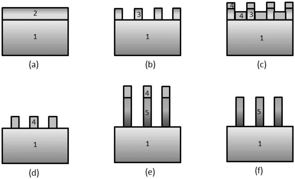
[0042] First, clean the Si or SiC substrate 1 with sulfuric acid and hydrogen peroxide at a volume ratio of 1:1, then use 5% hydrofluoric acid to etch and clean the Si or SiC substrate, and use an electron beam on the cleaned substrate surface The evaporation method evaporates a metal Al layer on the substrate layer to form an Al thin film 2, such as figure 2 As shown in (a), the thickness of the Al film 2 is 100-1000nm; the substrate evaporated with the Al film 2 is placed in a 0.5mol / L oxalic acid solution for electrochemical corrosion, and a porous aluminum oxide film is formed on the surface of the substrate. put the substrate with aluminum oxide film on the surface layer after electrochemical corrosion into 4% phosphoric acid by mass percentage and 2% chromic acid mixed solution for immersion, remove the aluminum oxide in contact with the substrate at t...


PUM

PropertyMeasurementUnit
Diameteraaaaaaaaaa
Lengthaaaaaaaaaa
Thicknessaaaaaaaaaa

Abstract

The invention proposes a reflective NEA GaN nanowire array photoelectric negative electrode and a manufacturing method therefor. The reflective NEA GaN nanowire array photoelectric negative electrode is obtained by growing p-type GaN nanowires on the surface of an Si or SiC substrate and performing Cs / O activation on a grown nanowire array. The reflective NEA GaN nanowire array photoelectric negative electrode comprises a substrate layer and a nanowire array emission layer positioned on the surface of the substrate layer, wherein the nanowire array emission layer consists of a plurality of p-type GaN nanowires; Cs / O activation layers are adsorbed on the surfaces of the p-type GaN nanowires; and the substrate layer is Si or SiC. According to the reflective NEA GaN nanowire array photoelectric negative electrode, the photoelectron transmission distance can be reduced while the material emission rate is reduced; and photons are fully absorbed by controlling the diameters of the nanowires, so that the quantum efficiency of the GaN photoelectric negative electrode is improved.

Description

technical field [0001] The invention belongs to the technical field of photoelectric emission materials, and in particular relates to a reflective NEAGaN nanowire array photocathode and a preparation method. Background technique [0002] A photocathode is a photoemissive material that converts light signals into electrical signals by using the external photoelectric effect. GaN photocathode with negative electron affinity, that is, the vacuum energy level on the surface of the cathode is lower than the bottom energy level of the conduction band, so the photoexcited electrons in the body only need to run to the surface, and can be emitted to the vacuum through tunneling, without excess kinetic energy to overcome The potential barrier on the surface of the material greatly increases the escape probability of photoexcited electrons, so it has unique advantages such as high quantum efficiency, small dark current, and concentrated energy distribution of emitted electrons. Its qu...

Claims


Application Information

Patent Timeline
IPC IPC(8): H01J1/34H01J9/02B82Y40/00B82Y30/00
CPCB82Y30/00B82Y40/00H01J1/34H01J9/022
Inventor 刘磊夏斯浩孔熠柯常本康张益军
Owner NANJING UNIV OF SCI & TECH
Learn More