
Calibration blackbody light source and preparation method thereof

A black body light source and calibration technology, applied in the infrared field, can solve the problems of high heating power consumption, large volume, heavy weight, slow heat dissipation, etc., and achieve the effects of fast cooling speed, easy integration, and small thermal mass

Active Publication Date: 2016-03-23
PROMISENSE ELECTRONICS TECH CO LTD +2
View PDF6 Cites 2 Cited by
  • Summary
  • Abstract
  • Description
  • Claims
  • Application Information

AI Technical Summary

Problems solved by technology

Although the heat pipe has a fast heating rate and heating uniformity, due to its large volume and weight, the heating power consumption is very high, often reaching hundreds of watts or even thousands of watts, and due to the large heat, the heat dissipation speed is very slow, which leads to calibration The actual time for the black body temperature to stabilize needs to reach 30-40 minutes
[0005] Although various infrared light source chips pursuing low power consumption and fast response have appeared in the field of infrared sensing, due to different uses, these chip structures are often designed as suspended thin film structures or other energy-saving structures, resulting in a significant gradient in the temperature of the radiation surface. distribution, so cannot be used as a calibration blackbody light source

Method used


Image

  • Calibration blackbody light source and preparation method thereof
  • Calibration blackbody light source and preparation method thereof
  • Calibration blackbody light source and preparation method thereof

Examples


Embodiment Construction

[0029] In order to make the object, technical solution and advantages of the present invention clearer, the present invention will be described in detail below in conjunction with the accompanying drawings and specific embodiments.

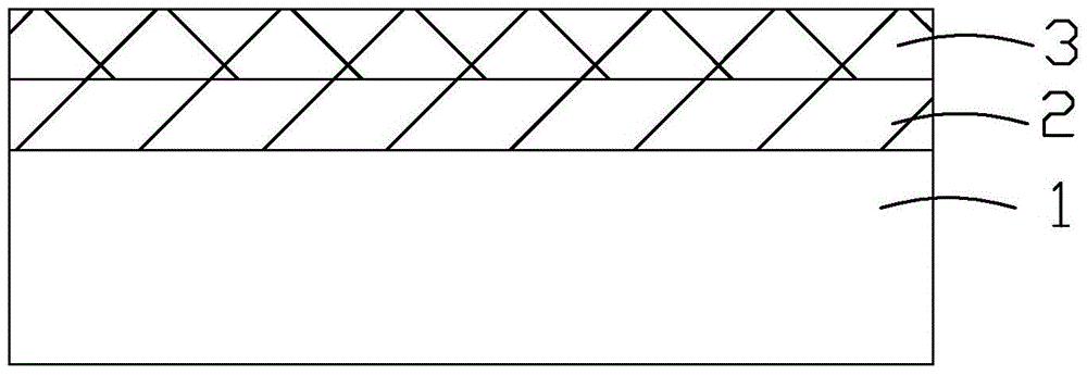
[0030] Please refer to Figure 1~Figure 7 Shown is the preparation method of the calibration black body light source of the present invention, comprises the following steps:

[0031] Provide a sheet-shaped substrate 1 with uniform thickness, and make a first insulating layer 2 with a certain thickness on the surface of the substrate 1; make a heating source on the surface of the first insulating layer 2 facing away from the substrate 1 3. The heating source 3 has a lead area 31 that can be electrically connected to an external circuit; a second insulating layer 4 of a certain thickness is fabricated on the surface of the heating source 3 facing away from the first insulating layer 2; Fabricate a temperature sensor 5 on the surface of the first in...


PUM

PropertyMeasurementUnit
power consumptionaaaaaaaaaa

Abstract

The invention provides a preparation method of a calibration blackbody light source. The preparation method comprises the following steps of providing a thin substrate and producing a first insulating layer on the surface of the substrate; producing a heating source on the surface of one side, far away from the substrate, of the first insulating layer, wherein the heating source comprises a lead wire region which can be electrically connected with an external circuit; producing a second insulating layer on the surface of one side, far away from the first insulating layer, of the heating source; producing a temperature sensor on the surface of one side, far away from the substrate, of the first insulating layer or the second insulating layer; forming a lead wire channel on one side, far away from the substrate, of the temperature sensor and forming a lead wire channel on one side, far away from the substrate, of the lead wire region, wherein each lead wire channel is exposed outwards and is electrically connected with the external circuit; and producing a blackbody film on the surface of one side, far away from the heating source, of the second insulating layer. The calibration blackbody light source is fast in warming and cooling rates; the required temperature stabilization time is just 5-10 min; the power consumption is just less than 50W for a light source chip with an area of 5 square centimeters when the radiation temperature is up to 500 DEG C; and the calibration blackbody light source is small in volume and is easily integrated at the interior of an imaging system.

Description

technical field [0001] The invention relates to the field of infrared technology, in particular to a preparation method of a calibrated blackbody light source and a calibrated blackbody light source integrating a blackbody film, a heating source and a temperature sensor. Background technique [0002] The calibration blackbody light source is an important part of the infrared scanner, and its performance will affect the quality of infrared imaging. Among them, the temperature control accuracy and temperature uniformity of the calibration blackbody light source are the key to whether the calibration blackbody light source can meet the test requirements. [0003] The traditional calibration blackbody light source is mainly composed of three parts: radiation blackbody, electric heat source, and temperature sensor. The radiation black body is generally made of a high-emissivity coating on a substrate with high thermal conductivity, and its surface emissivity is very close to 1; ...

Claims


Application Information

Patent Timeline
Patent Type & Authority Applications(China)
IPC IPC(8): B81C1/00B81B7/02
CPCB81C1/00015B81C1/0069
Inventor 俞骁张玉国孙红胜吴柯萱魏建强宋春晖郭安波
Owner PROMISENSE ELECTRONICS TECH CO LTD
Learn More