


Quick Research
Generate reliable direction feasibility study reports for your R&D in just a few steps.

Technical Q&A
Discover and master advanced knowledge NOW. Basics, ideas, possibilities, all at once.

Find Solutions
As an expert in R&D theories, this can generate solutions to your technical problems instantly.

Evaluate Feasibility
Analyze your overall solution with one click, know your potential R&D risks in advance.

Monitor Landscape
Get weekly tech updates, stay abreast of the latest tech innovations and key insights.
Conductive wire, manufacturing method of conductive wire, and wiring structure of conductive wire
A manufacturing method and a wiring structure technology, which are applied in the manufacture of cables/conductors, components of conductive cores, and traction of batteries/batteries, etc., can solve the problems of increased cost, difficulty in reducing the diameter of stranded wires, etc., and achieve good flexibility. , to achieve effective utilization, to achieve the effect of lightweight
- Summary
- Abstract
- Description
- Claims
- Application Information
AI Technical Summary
Problems solved by technology
Method used
Image

Examples
Embodiment 1
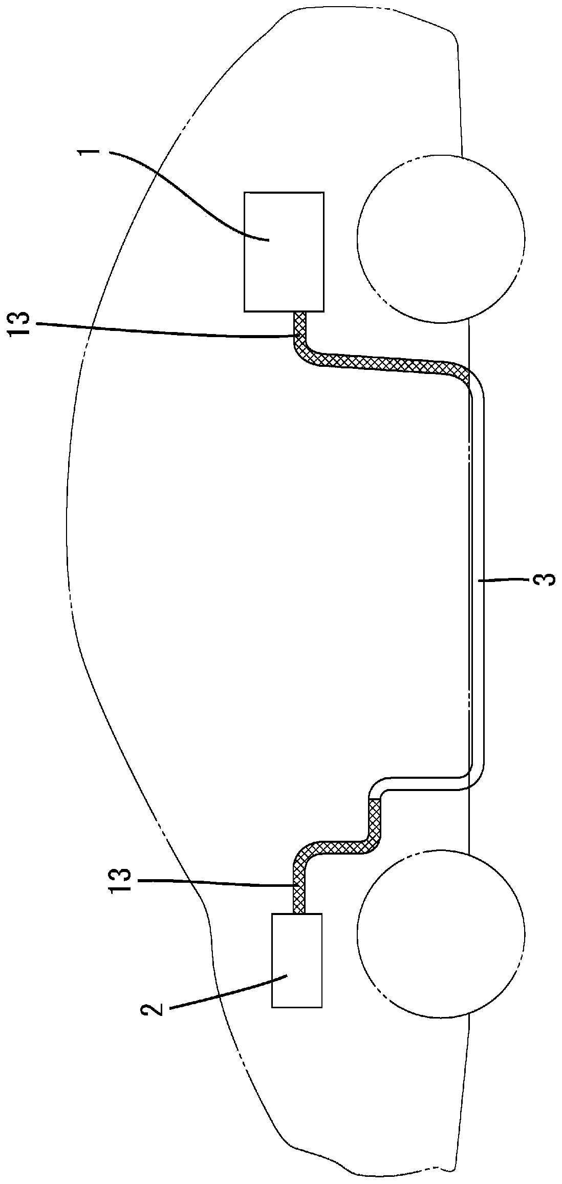
[0032] The conductive wire L of this embodiment is suitable for a hybrid vehicle. The battery 1 mounted on the rear side of the vehicle and the inverter 2 installed in the engine room are connected by a wire harness WH. In the case of this example, if Figure 4 As shown, the wire harness WH is composed of three conductive wires L.
[0033] The wire harness WH is collectively inserted into the shield pipe 3 arranged under the floor of the vehicle. More specifically, the rear end side of the shield pipe 3 is introduced into the rear suspension side of the vehicle compartment, and a metal braid 13 to be described later is interposed between the shield pipe 3 and the battery 1 . The middle of the shield pipe 3 extends substantially horizontally under the floor of the vehicle along the front-rear direction. Its front end is bent upward and introduced into the engine room, and extends toward the inverter 2 .
[0034] The shielding tube 3 is made of aluminum or an aluminum alloy,...
Embodiment 2
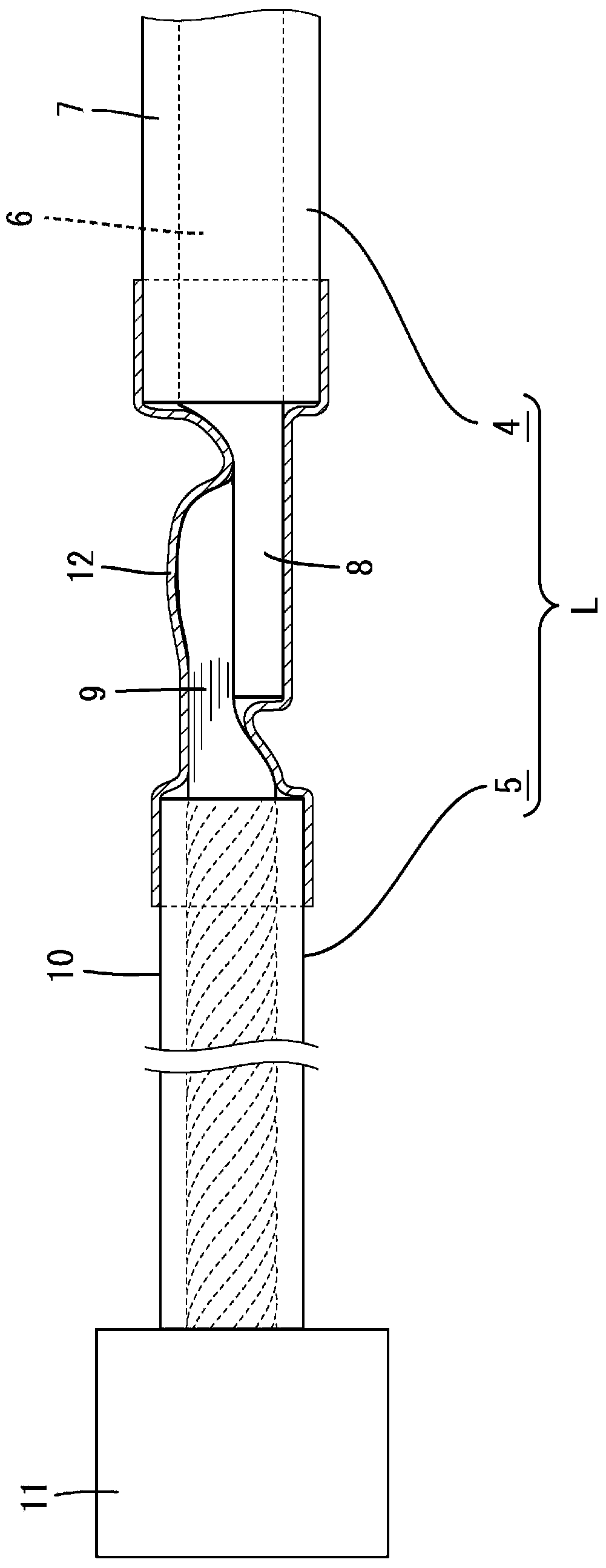
[0048] Figure 5 Example 2 of the present invention is shown. In Embodiment 1, the mode in which the conductor 6 exposed at the front end of the single-core wire 4 and the wire 9 exposed at the rear end of the twisted wire 5 are bonded and connected by ultrasonic welding is shown, but in Embodiment 2 connection by riveting. That is, the portion of the conductor 6 exposed from the single-core electric wire 4 is crushed and spread sufficiently in the width direction to form a pair of crimped portions 6A. The wire rod 9 portion of the twisted electric wire 5 is placed on the crushed portion 8 formed in this way, and both sides in the width direction are bent inward together and caulked. In this way it is also possible to connect single-core wires 4 and stranded wires 5 .
[0049] The other structures are the same as those in Embodiment 1, and can also exert the same effects.
Embodiment 3
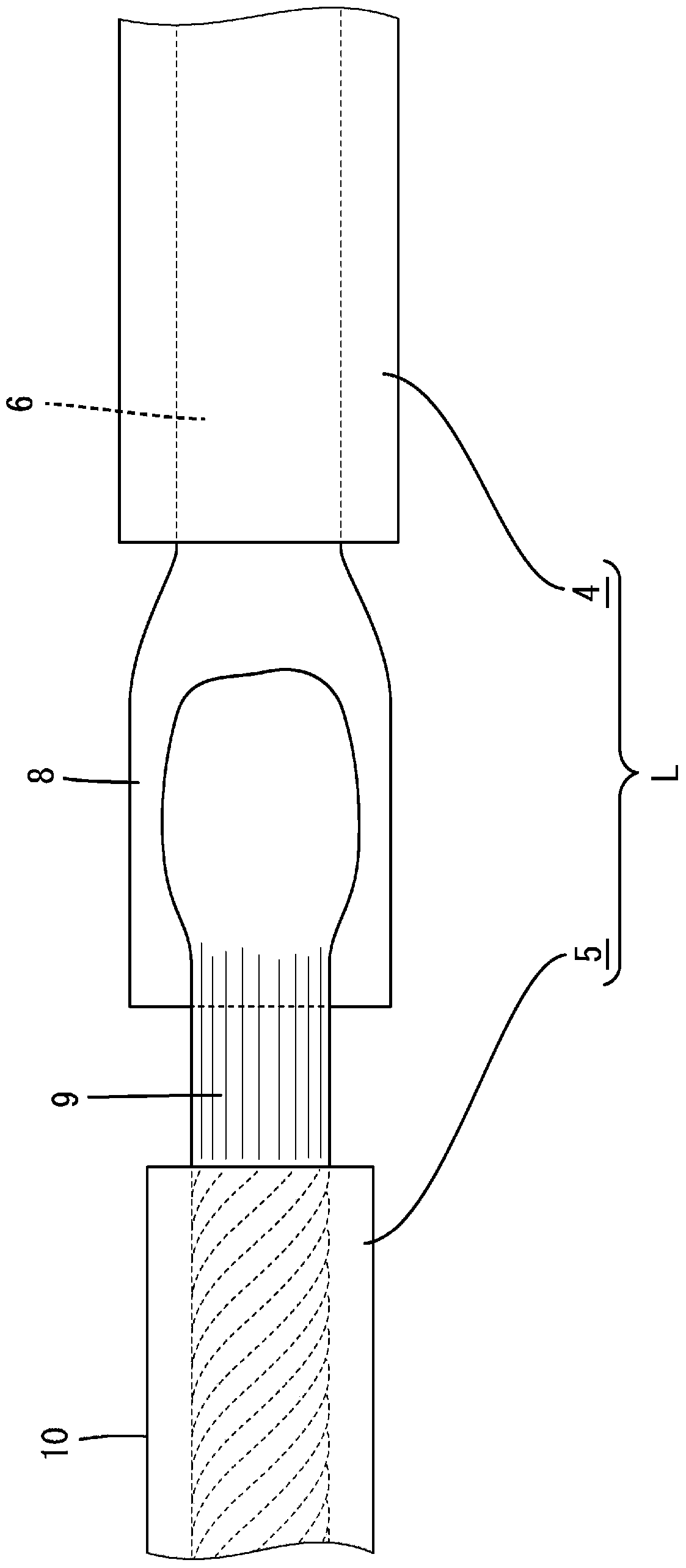
[0051] Image 6 Example 3 of the present invention is shown. In Example 2, the cross section of the conductor 6 was formed square and the wire 9 was riveted, but in Example 3 the cross section was formed circular and the wire 9 was riveted.
[0052] The other structures are the same as in Embodiments 1 and 2, and can also exert the same effect.
PUM
 Abstract
Description
Claims
Application Information
 - R&D Engineer
- R&D Manager
- IP Professional
- Industry Leading Data Capabilities
- Powerful AI technology
- Patent DNA Extraction
Browse by: Latest US Patents, China's latest patents, Technical Efficacy Thesaurus, Application Domain, Technology Topic, Popular Technical Reports.
© 2024 PatSnap. All rights reserved.Legal|Privacy policy|Modern Slavery Act Transparency Statement|Sitemap|About US| Contact US: help@patsnap.com