
Variable area capacitive-type bimodal optimized tuning-fork-type micromechanical gyroscope

A technology of mechanical gyroscope and variable area, which is applied in the direction of speed measurement by gyroscope effect, gyroscope/steering sensing equipment, measuring device, etc. It can solve the problems of difficult increase of frequency difference, non-linear displacement and capacitance conversion, and decrease of gyroscope sensitivity. , to achieve the effect of reducing quadrature coupling error, good decoupling performance, and solving small range

Inactive Publication Date: 2016-02-24
BEIJING INSTITUTE OF TECHNOLOGYGY
View PDF5 Cites 10 Cited by
  • Summary
  • Abstract
  • Description
  • Claims
  • Application Information

AI Technical Summary

Problems solved by technology

However, for the direct-coupled tuning fork gyro, regardless of the driving mode or the detection mode, the frequency of the in-phase mode is smaller than the frequency of the anti-phase mode, and the frequency difference between the two is difficult to increase
In order to reduce vibration sensitivity, the anti-phase operating frequency must be increased, which will inevitably lead to a decrease in gyro sensitivity
On the other hand, the variable-pitch offset comb differential detection introduces the nonlinear problem of displacement and capacitance conversion, and at the same time, the small pitch also brings the problem of small range

Method used


Image

  • Variable area capacitive-type bimodal optimized tuning-fork-type micromechanical gyroscope

Examples


Embodiment Construction

[0014] In order to further illustrate the technical means and effects taken by the present invention to achieve the expected purpose, so that the advantages and characteristics of the present invention can be more easily understood by those skilled in the art, the specific implementation methods, structural features and other aspects of the present invention will be described in conjunction with the accompanying drawings and examples. The efficacy is described in detail below.

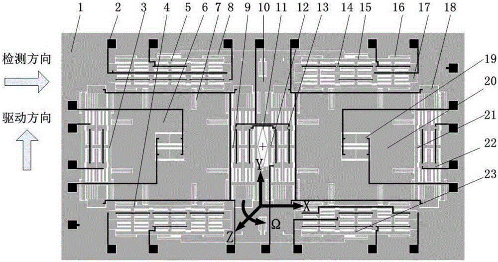
[0015] Such as figure 1 As shown, a variable-area capacitive dual-mode optimized tuning-fork micromechanical gyroscope disclosed in this embodiment includes a glass substrate 1 and a metal electrode 2; it also includes a MEMS structure, wherein a silicon chip is bonded on the glass substrate 1, Perform photolithography and deep etching on the silicon wafer on the glass substrate 1 to form anchor points 10, perform photolithography on the glass substrate 1, and sputter metal, form metal electrodes 2 by ...


PUM


Abstract

The present invention discloses a variable area capacitive-type bimodal optimized tuning-fork-type micromechanical gyroscope, relates to a tuning-fork-type micromechanical gyroscope, and belongs to the field of micro electro mechanical system (MEMS). The variable area capacitive-type bimodal optimized tuning-fork-type micromechanical gyroscope includes a glass substrate and a metal electrode; and further comprises a MEMS structure, the MEMS structure can fully use variable area detection comb differential capacitances in a space structure to increase the arrangement number of the variable area detection comb differential capacitances in a limited space. Modal optimization of a detection mode can be realized by connection of an anchor point and a coupled rhombus beam, and modal optimization of a drive mode can be realized by connection of the anchor point and a lever. A U-shaped beam can be used to reduce puadrature coupling error brought by dimension error caused by processing technology defects. The variable area capacitive-type bimodal optimized tuning-fork-type micromechanical gyroscope can realize the modal optimization of the drive mode and the detection mode, can realize the linear conversion of detection capacitance variation and displacement variation under the premise of no reducing of the sensitivity, can effectively solve the small measuring range problem of a varied spacing capacitance microgyroscope, and can reduce the quadrature coupler error.

Description

technical field [0001] The invention discloses a tuning fork micro-mechanical gyroscope with variable area capacitive dual-mode optimization, relates to a tuning fork micro-mechanical gyroscope, especially relates to a variable-area capacitive dual-mode optimized tuning fork micro-mechanical gyroscope, which belongs to the micro-electromechanical system (MEMS) technology field. Background technique [0002] Micromechanical gyroscopes are developing rapidly and have been widely used in the electronics industry, automobiles, inertial navigation and other fields, thanks to their advantages of small size, low cost, low energy consumption and mass production. The working principle of the vibrating micromachined gyroscope is based on the Coriolis effect, which uses the energy transfer between the driving mode and the detection mode to be sensitive to changes in angular velocity. [0003] With the continuous improvement of the performance (resolution, sensitivity, bandwidth) of th...

Claims


Application Information

Patent Timeline
IPC IPC(8): G01C19/5621
CPCG01C19/5621
Inventor 管延伟高世桥刘海鹏李平
Owner BEIJING INSTITUTE OF TECHNOLOGYGY
Learn More