Multi-roll multi-chamber winding coating device

A technology of a coating device and a coating chamber, which is applied in sputtering coating, vacuum evaporation coating, ion implantation coating and other directions, can solve the problems of inability to obtain high-quality coating, difficulty in obtaining high-quality coating, and prolonged coating cycle, etc. , to achieve the effect of repeatability and stability, shortening the vacuuming time and saving space

Active Publication Date: 2018-11-02
广东腾胜科技创新有限公司
View PDF7 Cites 0 Cited by
  • Summary
  • Abstract
  • Description
  • Claims
  • Application Information

AI Technical Summary

Problems solved by technology

This makes it necessary to break the vacuum once every coating furnace, and the winding roller, unwinding roller and coating area are all in the atmosphere, so that the coating area will absorb water vapor and dust in the air and cause pollution. Therefore, it is difficult to obtain high-quality coatings
In addition, every furnace in the coating chamber needs to be evacuated again, the coating cycle is lengthened, and the production efficiency is low
At the same time, after the vacuum is broken, the reaction gas or protective gas needs to be refilled for each plating furnace, and the processing cost is high.
[0005] In the existing flexible circuit board coating equipment, the sputtering target is used to surround the water-cooled drum to coat the film layer. Each sputtering target is in the same vacuum environment, which is prone to diffraction contamination of the target material, and high-quality coatings cannot be obtained. film layer, especially when the surface of the winding substrate requires a variety of coating layers with different properties, this phenomenon is more obvious

Method used


Image

  • Multi-roll multi-chamber winding coating device
  • Multi-roll multi-chamber winding coating device
  • Multi-roll multi-chamber winding coating device

Examples


Embodiment 1

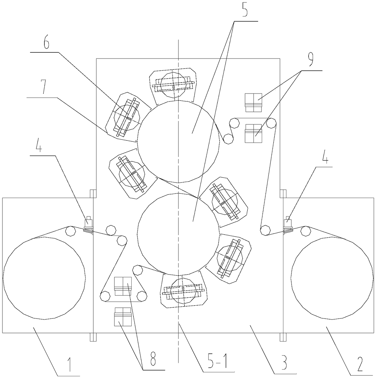
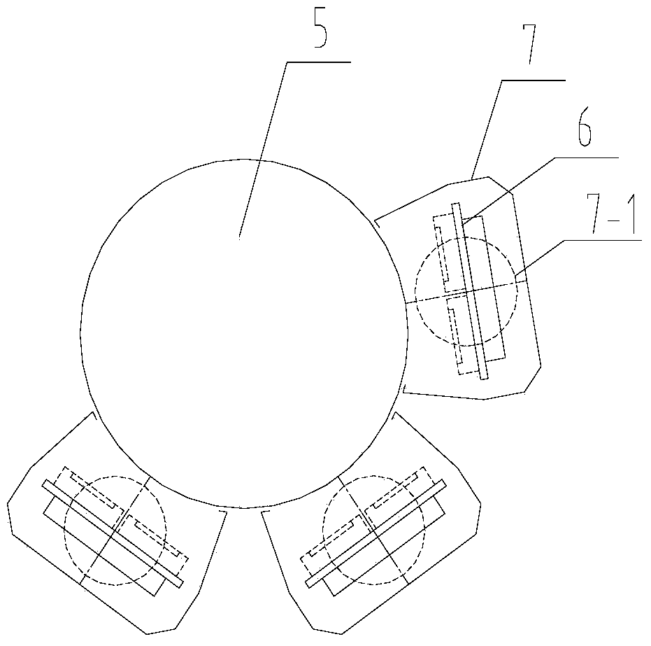
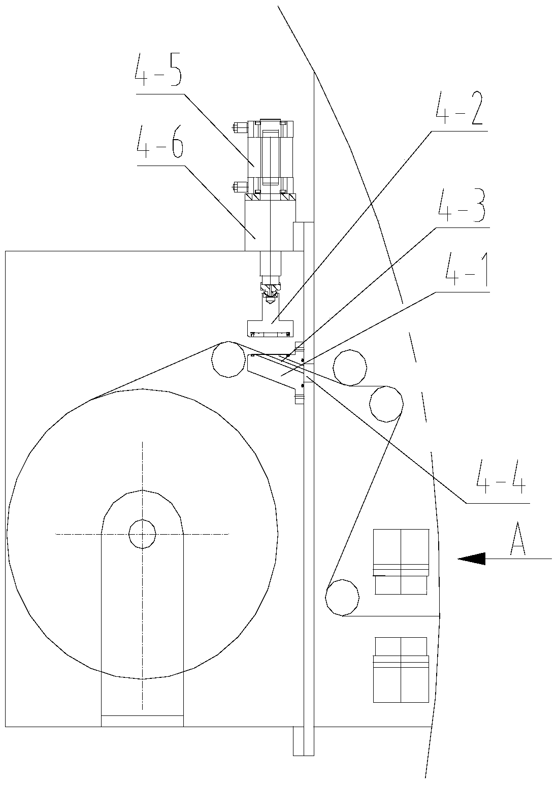
[0035] In this embodiment, a multi-roller multi-chamber winding coating device, such as figure 1As shown, it includes a plurality of independent vacuum chambers. The plurality of vacuum chambers include an unwinding chamber 1, a winding chamber 2 and a coating chamber 3. The unwinding chamber and the winding chamber are respectively arranged on both sides of the coating chamber. Any two A vacuum lock 4 is arranged between two adjacent vacuum chambers; two water-cooled drums 5 distributed up and down are arranged in the coating chamber, and at least two sputtering targets 6 are distributed on one side of each water-cooled drum, each sputtering target A target cover 7 is arranged on the outer periphery, and a gap for the winding substrate to pass is provided between the bottom of the target cover and the surface of the water-cooled drum, and each target cover is respectively connected with a vacuum unit, and an independent sputtering chamber is formed inside each target cover. W...

Embodiment 2

[0043] In this embodiment, a multi-roller multi-chamber winding coating device has a structure such as Figure 5 Shown, compared with embodiment 1, its difference is: there are two coating chambers, respectively the first coating chamber and the second coating chamber; the two water-cooled drums in the first coating chamber are the first upper water-cooled drum and The first lower water-cooled drum, three sputtering targets are distributed on the left side of the first upper water-cooled drum, and three sputtering targets are distributed on the right side of the first lower water-cooled drum; the two water-cooled drums in the second coating chamber are the second upper water-cooled Drum and the second lower water-cooled drum, three sputtering targets are distributed on the right side of the second upper water-cooled drum, and three sputtering targets are distributed on the left side of the second lower water-cooled drum.

[0044] When the multi-roller and multi-chamber winding...

Embodiment 3

[0046] In this embodiment, a multi-roller multi-chamber winding coating device has a structure such as Figure 6 Shown, compared with embodiment 1, its difference is: there are two coating chambers, respectively the first coating chamber and the second coating chamber; the two water-cooled drums in the first coating chamber are the first upper water-cooled drum and The first lower water-cooled drum, two sputtering targets are distributed on the left side of the first upper water-cooled drum, and two sputtering targets are distributed on the right side of the first lower water-cooled drum; the two water-cooled drums in the second coating chamber are the second An upper water cooling drum and a second lower water cooling drum, two sputtering targets are distributed on the right side of the second upper water cooling drum, and two sputtering targets are distributed on the left side of the second lower water cooling drum.

[0047] When the multi-roller and multi-chamber winding co...


PUM


Abstract

The invention discloses a multi-roller and multi-chamber coiling film coating device. The device comprises a plurality of vacuum chambers which are independent from each other, wherein the plurality of vacuum chambers include an uncoiling chamber, a coiling chamber and at least one film coating chamber; the uncoiling chamber and the coiling chamber are correspondingly arranged at two sides of the film coating chamber; a vacuum lock is arranged between any two adjacent vacuum cambers; a plurality of water cooling drums which are correspondingly distributed on the top and at the bottom are arranged in the film coating chamber; at least two sputtering targets are distributed at one side of each water cooling drum; a target cover is arranged in the periphery of each sputtering target; a gap through which a coiled base material can pass is formed between the bottom part of each target cover and the surface of the corresponding water cooling drum; an independent sputtering chamber is formed in each target cover. According to the device, the film coating processes in adjacent film coating chambers are completely separated; the film coating chambers can be arranged according to the quantity of film layers and different types of the film layers; a multi-film composite film can be coated within one working cycle; in addition, the gas isolation of sputtering areas can be also achieved, thus the back flow of gas can be avoided, and as a result, the quality of a product can be improved.

Description

technical field [0001] The invention relates to the technical field of coil surface coating, in particular to a multi-roller and multi-chamber winding coating device. Background technique [0002] The flexible intelligent electrochromic film is a new type of electrochromic material, which has the ability to adjust light absorption and transmission under the action of an electric field, and can selectively absorb or reflect external thermal radiation and internal thermal diffusion, reducing summer maintenance. A lot of energy must be consumed to keep cool and warm in winter, and at the same time improve the natural light level and prevent privacy. At present, it is commonly used in color-changing applications such as smart windows, anti-glare rearview mirrors, dimming glass on high-end cars and airplanes, and is a product with a large market demand. [0003] For the processing of flexible intelligent electrochromic, photochromic, and thermochromic films, the traditional meth...

Claims


Application Information

Patent Timeline
Patent Type & Authority Patents(China)
IPC IPC(8): C23C14/56C23C14/34
Inventor 朱文廓朱刚劲朱刚毅
Owner 广东腾胜科技创新有限公司
Why Eureka
Try Eureka