
PN junction dyeing method

An all-round, sample technology, applied in electrical components, circuits, semiconductor/solid-state device testing/measurement, etc., can solve the problem of poor junction analysis in the guard ring area, indistinguishable PN junctions in the guard ring area, and no staining. The effect of knot effect and other issues can be achieved to achieve the effect of obvious effect and clear appearance.

Inactive Publication Date: 2016-02-03
SHANGHAI HUAHONG GRACE SEMICON MFG CORP
View PDF2 Cites 4 Cited by
  • Summary
  • Abstract
  • Description
  • Claims
  • Application Information

AI Technical Summary

Problems solved by technology

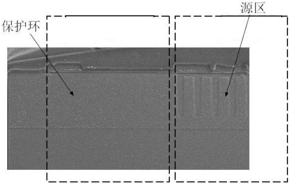
The existing methods can better correspond to the analysis of the junction in the source region, but the effect of the junction analysis in the guard ring region is not good, such as image 3 and Figure 4 as shown, image 3 The micrograph showing the dyeing effect of the protection ring area and the source area shows a very obvious gap between the protection ring area and the source area, as shown in Figure 4 In the enlarged picture shown, the PN junction in the guard ring area is basically indistinguishable, and there is no dyeing effect

Method used


Image

  • PN junction dyeing method
  • PN junction dyeing method
  • PN junction dyeing method

Examples


Embodiment Construction

[0029] The PN knot dyeing method of the present invention comprises the following steps:

[0030] Step 1: After the surface of the sample to be analyzed is protected, the cross section of the groove is ground, and the protective rings at both ends are ground, and the protective rings are ground at both ends until the groove in the source area is completely exposed. Grinding leaves only parallel grooves on the sample. The trenches include guard ring trenches parallel to each other and source trenches, and the guard rings perpendicular to the source trenches are ground away so that the cross-section of the source trenches is fully exposed. Such as Figure 5 shown. This step will affect the effect of the subsequent gold plating layer on dyeing.

[0031] In the second step, the protective ring area of ​​the ground sample is protected in all directions, and the surface and the back of the unprotected area are gold-plated with a gold plating machine. For example, use the HITACHIE...


PUM

PropertyMeasurementUnit
Thicknessaaaaaaaaaa

Abstract

The invention discloses a PN junction dyeing method comprising the steps that step one, protection is formed on the surface of a sample to be analyzed and then protection rings of two ends are ground in the cross section direction of a groove so that the sample only having the protection rings parallel to the source region groove is obtained; step two, the protection rings of the ground sample are comprehensively protected through the protection layer, and gold plating is performed on the surface and the back surface of regions without protection by using a gold plating machine; step three, the protection rings of the ground sample are comprehensively protected, and gold plating is performed on the front surface and the back surface of the cross section of the regions without protection by using the gold plating machine; and step four, the protection layer is removed, and normal temperature junction dyeing is performed in the mixed liquid of hydrofluoric acid, nitric acid and acetic acid and then SEM analysis is performed. Gold plating is performed on the super junction source region and blocking is performed on the projection rings so that P-type and N-type conductivity difference of a protection ring region can be enhanced and the junction dyeing effect can be enhanced.

Description

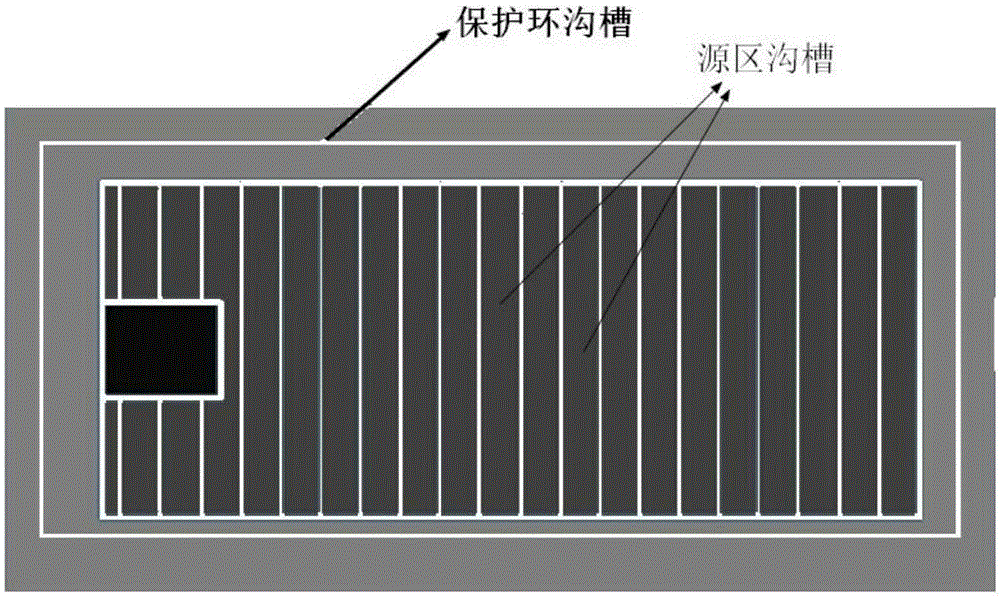
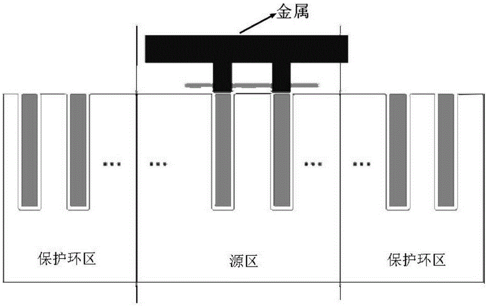
technical field [0001] The invention relates to the field of semiconductor integrated circuit manufacturing, namely a PN junction dyeing method, in particular to a super junction and guard ring PN junction dyeing method. Background technique [0002] The PN junction is the basis of integrated circuit work, and the analysis of the PN junction is of great significance for chip failure analysis, process monitoring, and process improvement. The general super junction guard ring and source region PN junction morphology are as follows: figure 1 and figure 2 as shown, figure 1 is a top view, figure 2 is a sectional view. The chemical dyeing method is a common method in PN junction analysis. [0003] For chemical dyeing and knotting, the factors found to determine the dyeing effect are: 1. Chemical reagents; 2. The inherent characteristics of PN junctions, such as the size of the junction, doping concentration, etc.; 3. The process of dyeing and knotting, such as temperature ...

Claims


Application Information

Patent Timeline
IPC IPC(8): H01L21/66
CPCH01L22/24
Inventor 芮志贤赖华平
Owner SHANGHAI HUAHONG GRACE SEMICON MFG CORP
Learn More