Laser car fog lamp optical system formed by combining diffraction optical element and laser device

A diffractive optical element and optical system technology, applied in refractors, optical signals, electric light sources, etc., can solve problems such as the inability to realize the illumination light field, high requirements for the application environment, and restrictions on product market applications, so as to achieve high light utilization efficiency , low cost, improved functionality and applicability

Inactive Publication Date: 2016-02-03
ZHEJIANG UNIVERSITY OF SCIENCE AND TECHNOLOGY +1
View PDF12 Cites 1 Cited by
  • Summary
  • Abstract
  • Description
  • Claims
  • Application Information

AI Technical Summary

Problems solved by technology

The traditional design method is to modulate the incident light field by means of refraction, occlusion, and imaging. The design method has complex optical elements, a large number, very low light utilization efficiency, and single function, which cannot realize complex lighting light fields. For example, for new application fields such as automobile fog lamps with large inclination angles, asymmetric correction of light intensity distribution, and long-distance fog lamps over 100 meters, traditional design methods cannot be realized.
At the same time, the traditional lighting light field design method has large optical devices, high cost, and high requirements for the application environment. Fine dust on the surface of the optical device will cause serious defects in the special-shaped light field. The above factors have caused many problems for the use of this product. Unfavorable factors seriously limit the market application of the product

Method used


Image

  • Laser car fog lamp optical system formed by combining diffraction optical element and laser device
  • Laser car fog lamp optical system formed by combining diffraction optical element and laser device
  • Laser car fog lamp optical system formed by combining diffraction optical element and laser device

Examples


Embodiment 1

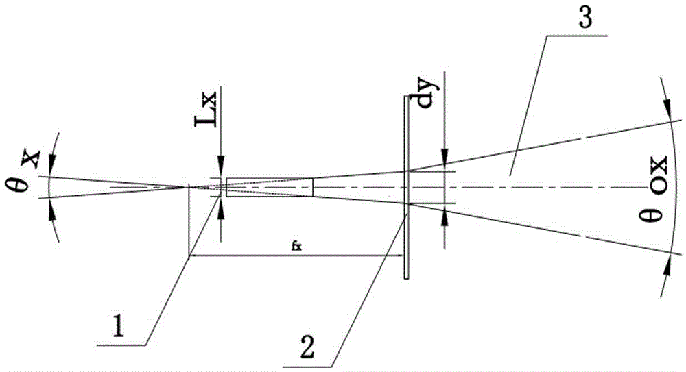
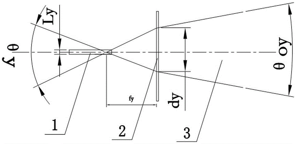
[0025] The laser is selected as a divergent laser (such as a semiconductor laser), and the emitted laser has a certain difference in the divergence angle θx in the X direction and the divergence angle θy in the Y direction, and the luminous size Lx and Ly of the laser are also quite different. The difference is very large, θx is about 40 degrees, θy is about 10 degrees, Lx is 1um, and Ly is 100um.

[0026] The laser is selected as a divergent laser (such as a semiconductor laser). The laser spot emitted by the laser has a certain difference in the X-direction size dx and the Y-direction size dy due to the influence of θx and θy. For example, the dx and dy of a semiconductor laser There is a big difference, dx=Lx+tan(θx / 2)×2×D, dy=Ly+tan(θy / 2)×2×D, where D is the distance between the laser spot test position and the laser light-emitting position .

[0027] In order to achieve a good lighting effect of automobile fog lamps, it is necessary to design diffractive optical elements...

Embodiment 2

[0032] The laser is selected as a collimated parallel light laser. The emitted laser has a very small divergence angle θx in the X direction and a divergence angle θy in the Y direction, both of which are very small angles close to 0. The laser beam presents the propagation mode of parallel light , whose wavefront is a plane wave.

[0033] The laser is selected as a collimated parallel light laser. The laser emitted by the laser has a certain difference in the X-direction dimension dx and the Y-direction dimension dy. For example, the dx and dy of the semiconductor laser compressed by the divergence angle of the aspheric lens are different. dx: dy=1:5.

[0034] In order to achieve a good lighting effect of automobile fog lamps, it is necessary to design diffractive optical elements according to the characteristics of the above-mentioned semiconductor lasers.

[0035] Function 1 of the diffractive optical element in this embodiment: the design incorporates the design for plane...


PUM


Abstract

The invention discloses a laser car fog lamp optical system formed by combining a diffraction optical element and a laser device. The laser car fog lamp optical system comprises a laser illuminating light source and the diffraction optical element, wherein the laser illuminating light source is a divergency light source or a collimating parallel light source, and the diffraction optical element is designed according to parameters of the laser illuminating light source and used for achieving optical field distribution required by the optical system. The diffraction optical element has the characteristics of being small in size, easy to mount and low in cost and can greatly reduce the size of the optical system and reduce the cost of an optical product. Meanwhile, according to the diffraction optical element, the optical indicatrix allowance is large, the influence of fine dust and dirt of a light pass area on an abnormal-shaped optical field is quite small, the requirement for the application environments is low, the element can adapt to various complex application environments, an adjusting system with high light utilization efficiency of the optical field, low cost, simple optical structure design, small size and high-accuracy divergence angle is completely achieved, and the functions and applicability of the optical system are improved.

Description

technical field [0001] The invention belongs to the field of optics, and in particular relates to a laser automobile fog light optical system using a combination of diffractive optical elements and lasers. Background technique [0002] In modern technology, with the application and development of the automobile market, auto parts products and corresponding optoelectronic equipment and systems, the application of optoelectronic products in the auto parts application market is becoming more and more extensive, and the requirements for the technical indicators of optoelectronic products are also getting higher and higher. Among them According to specific application requirements, the application market of laser fog lamp lighting field with special pattern is developing rapidly, such as fog lamp products with long-distance oblique irradiation, special pattern car fog lamp products, and fog lamp products with large angle outside the bottom of the car, etc. The development of prod...

Claims


Application Information

Patent Timeline
IPC IPC(8): F21S8/10F21V19/00F21V5/04F21W101/10
CPCF21S43/00F21V5/045F21V19/00F21W2102/00
Inventor 田克汉尹晓东霍轶杰潘卫清贲宇
Owner ZHEJIANG UNIVERSITY OF SCIENCE AND TECHNOLOGY
Why Eureka
Try Eureka