
Secondary electro-optic crystal with gradient refractive index effect as well as preparation method and application method of secondary electro-optic crystal

A gradient refractive index and secondary electro-optic technology, applied in crystal growth, chemical instruments and methods, single crystal growth, etc.

Active Publication Date: 2016-01-06
山东山科智晶光电科技有限公司
View PDF3 Cites 14 Cited by
  • Summary
  • Abstract
  • Description
  • Claims
  • Application Information

AI Technical Summary

Problems solved by technology

Therefore, in theory, for pure KTN crystals, the excellent and practical electro-optic effect and gradient refractive index performance cannot be obtained at the same time.

Method used


Image

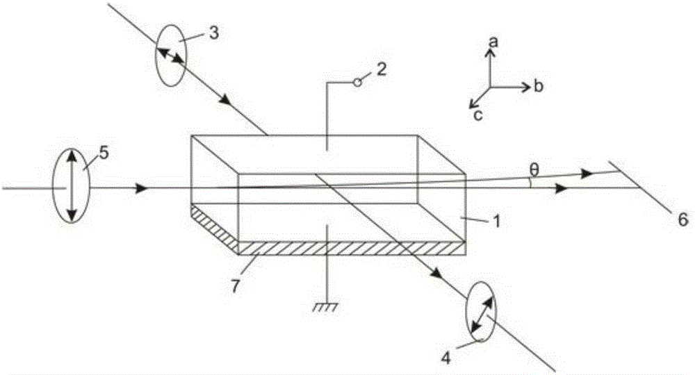
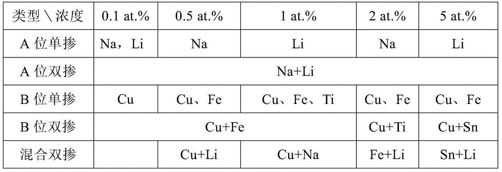
  • Secondary electro-optic crystal with gradient refractive index effect as well as preparation method and application method of secondary electro-optic crystal
  • Secondary electro-optic crystal with gradient refractive index effect as well as preparation method and application method of secondary electro-optic crystal

Examples


Embodiment 1

[0041] Example 1: Cu:KTa 0.67 Nb 0.33 o 3 (Cu doping amount 0.25at%)

[0042] high purity K 2 CO 3 、 Ta 2 o 5 , Nb 2 o 5 According to the molar ratio K 2 CO 3 : Ta 2 o 5 :Nb 2 o 5 =1.25:0.34:0.66 Weigh the ingredients, press CuO:(Ta 2 o 5 +Nb 2 o 5 ) / 2=0.25:100 molar ratio to calculate the weight of doped ion CuO powder, and mix it uniformly, put it into a platinum crucible after briquetting, and sinter in a muffle furnace at 1075°C for more than 24 hours to obtain Cu:KTN polycrystalline material About 1000 grams, put the Cu:KTN polycrystalline material in a platinum crucible, and carry out crystal growth in the atmosphere. After the process of seeding, necking, shouldering, and equal diameter growth, block Cu:KTa is obtained. 0.67 Nb 0.33 o 3 crystals.

[0043] Present embodiment gained Cu:KTa 0.67 Nb 0.33 o 3 crystal, the matrix component Ta / Nb is uniformly distributed in the crystal, and the doped ion Cu 2+ Inside the crystal, the distribution is li...

Embodiment 2

[0044] Example 2: Cu:KTa 0.63 Nb 0.37 o 3 (Cu doping amount 0.5at%)

[0045] The crystal growth preparation process of this example is basically similar to Example 1, the difference is that the ratio of raw materials is adjusted to K 2 CO 3 : Ta 2 o 5 :Nb 2 o 5 =1.25:0.31:0.69, the total mass of polycrystalline material is about 1000 grams, CuO:(Ta 2 o 5 +Nb 2 o 5 ) / 2 Weighing at a molar ratio of 0.25:100, the synthesis and sintering temperature of the polycrystalline material was adjusted to 1025° C., and the crystal growth process was the same as in Example 1. The resulting Cu:KTa 0.63 Nb 0.37 o 3 Cu in crystal 2+ It is distributed linearly and decreasingly along the c-axis direction, the ion concentration gradient is about 0.15at% / cm, and the corresponding crystal refractive index gradient is about 4×10 -3 / mm.

Embodiment 3

[0046] Embodiment 3: Fe:KTa 0.61 Nb 0.39 o 3 (Fe doping amount 1at%)

[0047] The crystal growth preparation process of this example is basically the same as that of Example 1, the difference is that the ratio of raw materials is adjusted to K 2 CO 3 : Ta 2 o 5 :Nb 2 o 5 =1.2:0.29:0.71, doped ion iron oxide according to Fe 2 o 3 :( 2 o 5 +Nb 2 o 5 ) was weighed at a molar ratio of 1:100, the synthesis and sintering temperature of the polycrystalline material was adjusted to 1000° C., and the crystal growth process was the same as in Example 1. Obtained Fe:KTa 0.63 Nb 0.37 o 3 Fe in crystal 3+ It is distributed linearly and decreasingly along the c-axis direction, the ion concentration gradient is about 0.3at% / cm, and the corresponding crystal refractive index gradient is about 3×10 -3 / mm.


PUM

PropertyMeasurementUnit
Refractive index valueaaaaaaaaaa

Abstract

The invention specifically relates to a secondary electro-optic crystal with a gradient refractive index effect as well as a preparation method and an application method of the secondary electro-optic crystal. The secondary electro-optic crystal is an ion doped electro-optic crystal with a general formula of M: KTa[1-x]NbxO3, and has a perovskite structure, wherein M=Cu<2+>, Fe<3+>, Sn<4+>, Ni<2+>, Ti<4+>, Na<+> and Li<+>, and the content of M is 0-5at%; the content x of Nb in a crystal component is more than or equal to 0 and less than or equal to 5, a curie point is positioned between -241 and 90 DEG C, the crystal above the curie point is a cubic phase and an m3m point group; and the crystal below the curie point becomes a tetragonal phase and a 4mm point group, a matrix component Ta / Nb is uniformly distributed in the crystal, doped ions M are in non-uniform distribution in the crystal, and the concentration distribution changes linearly along the growth direction of the crystal. The invention realizes functional combination of an electro-optic effect and a gradient refractive index effect of the crystal, and respectively realizes modulation of propagation direction and intensity of laser in different directions of the same modulation sample.

Description

technical field [0001] The invention belongs to the technical field of functional crystal material preparation and laser modulation, and specifically relates to a secondary electro-optic crystal with gradient refractive index effect and its preparation and application method. Background technique [0002] Laser technology is one of the most important cutting-edge technologies in the country's medium and long-term scientific and technological development plan. As one of the core contents of laser technology, laser modulation technology is of great significance to its application and development. Laser modulation is mainly to achieve a specific output effect by adjusting the phase, intensity or amplitude of the laser. Commonly used laser modulation methods include mechanical modulation, electro-optic modulation, acousto-optic modulation, passive modulation, etc. Among them, electro-optic modulation has the advantages of high efficiency, good stability, fast response, easy cont...

Claims


Application Information

Patent Timeline
IPC IPC(8): C30B29/22C30B15/00
Inventor 王旭平刘冰杨玉国吕宪顺张园园魏磊王继扬
Owner 山东山科智晶光电科技有限公司
Learn More