
Manufacturing method of welded product, welding method, welding device

A manufacturing method and welding current technology, which are applied in welding/welding/cutting items, welding equipment, manufacturing tools, etc., can solve the problems of pits and pores, pore defects, lack of pore suppression effect, and inability to be fully stirred, etc. To achieve the effect of suppressing porosity defects

Active Publication Date: 2017-07-14
KOBE STEEL LTD
View PDF2 Cites 0 Cited by
  • Summary
  • Abstract
  • Description
  • Claims
  • Application Information

AI Technical Summary

Problems solved by technology

[0010] However, in fillet welds in which welded joints occupy most of the above fields, there is such a problem that the primer coated on the surface of the steel plate evaporates during welding and immerses in the molten pool, and the surface and inside of the weld metal (weld) , Pore defects such as pits and pores are prone to occur
However, in welding using flux-cored wire, unlike welding using solid wire, the surface of the molten pool is covered with highly viscous slag, so the molten metal is still bound by the slag and cannot be absorbed by simply adding a magnetic field. Stir well, and there may be cases where the pore suppression effect cannot be obtained

Method used

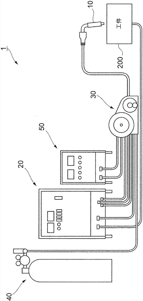
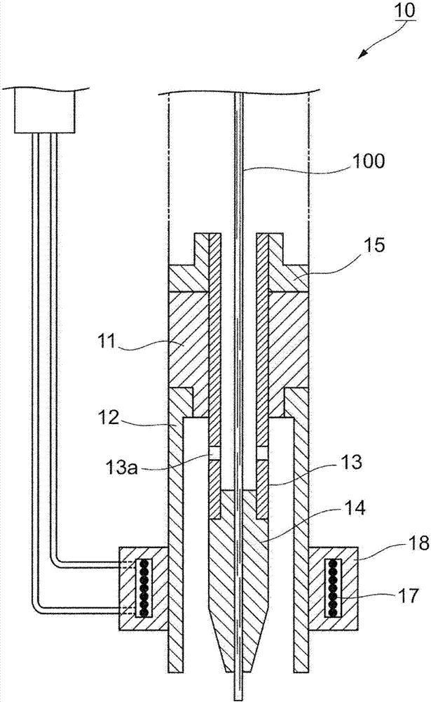
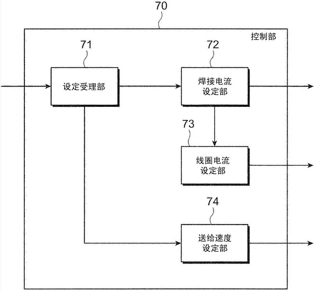

Image

  • Manufacturing method of welded product, welding method, welding device
  • Manufacturing method of welded product, welding method, welding device
  • Manufacturing method of welded product, welding method, welding device

Examples


Embodiment

[0100] Hereinafter, the present invention will be described in more detail based on examples. However, the present invention is not limited to the following examples unless the gist is exceeded.

[0101] In addition, here, the basic welding conditions are as follows.

[0102] ・The first steel plate 201 and the second steel plate 202: JISG3106SM490A inorganic zinc primer coating (coating thickness 30μm), 12mmt×75mmW×475mmL

[0103] ·Inclination angle of welding torch 10: 45°

[0104] Protrusion length of the flux-cored welding wire 100 from the welding torch 10: 25 mm

[0105] Target position: root

[0106] ·Diameter of flux cored wire 100:

[0107] [Relationship between welding current and magnetic flux density]

[0108] First, the present inventors studied the relationship between the welding current I (average value) supplied to the flux-cored wire 100 and the magnetic flux density B (effective value) of the alternating magnetic field supplied to the molten pool 400 i...


PUM

PropertyMeasurementUnit
thicknessaaaaaaaaaa

Abstract

In gas-shielded arc welding using a primer-coated steel sheet as a base material and using an active gas and a flux-cored wire, occurrence of poor appearance of the welded part due to porosity defects originating from the primer is suppressed. In a method for producing a welded product in which a first steel plate and a second steel plate made of a primer-coated steel plate are arranged in a T-shape and welded at the corners formed at the two places, the inner side of the outer skin made of steel is filled with flux. The flux-cored wire (100) and the shielding gas (carbon dioxide) are formed, and the welding current is supplied to the corner by the flux-cored wire (100) through the arc under the shielding gas, and a molten pool (400) is formed at the corner, and for the welding An alternating magnetic field is applied to the pool, so that the welding current (A) and the magnetic flux density (mT) of the alternating magnetic field have the relationship of 20000≤welding current×magnetic flux density≤30000, and the welding current and alternating magnetic field are set in this way.

Description

technical field [0001] The present invention relates to a manufacturing method of a welded object, a welding method, and a welding device. Background technique [0002] In the manufacturing fields such as ships and bridges, welding construction using flux-cored wire plays an important role in the manufacturing process. [0003] In this field, gas-shielded arc welding (mainly carbon dioxide arc welding) is used, in which a shielding gas mainly composed of carbon dioxide is supplied from a welding torch, a flux-cored welding wire is fed to the welding torch, and the flux-cored welding wire is welded. In the supply of electric current, an arc is generated between the flux-cored wire and the base metal in a shielding gas to perform welding (refer to Patent Document 1). [0004] In addition, in the field of manufacturing automobiles and the like, gas-shielded arc welding (mainly mixed gas arc welding) is known in which a shielding gas mainly composed of an inert gas such as argo...

Claims


Application Information

Patent Timeline
Patent Type & Authority Patents(China)
IPC IPC(8): B23K9/08B23K9/02B23K9/173B23K9/23B23K35/30B23K35/368
CPCB23K9/08B23K9/173B23K9/23B23K35/30B23K35/368B23K35/40B23K35/0255B23K35/0261B23K35/0266B23K35/24B23K9/025B23K2101/34B23K2103/04B23K35/325B23K35/38B23K9/164B23K37/00
Inventor 山崎圭袁倚旻铃木励一
Owner KOBE STEEL LTD
Learn More