
High-performance ceramic ball valve

A ceramic ball valve, high-performance technology, applied to valve devices, cocks including cut-off devices, engine components, etc. The effect of avoiding safety hazards and simple structure

Inactive Publication Date: 2015-12-02
SANBORA VALVE
View PDF6 Cites 5 Cited by
  • Summary
  • Abstract
  • Description
  • Claims
  • Application Information

AI Technical Summary

Problems solved by technology

[0002] The valves commonly used in various industries in China are metal valves. The use of metal valves has a history of hundreds of years. Although metal valves have been improved in structure and materials, they cannot adapt to the increasingly high wear and tear due to the limitations of metal material properties. Corrosion and other harsh working conditions are mainly reflected in the short service life and serious leakage, which greatly affect the stability of the system operation; traditional metal valves urgently need to be completely innovated in terms of materials, design and manufacturing processes; however, ceramic materials are due to their own Physical properties, it has excellent chemical corrosion resistance, wear resistance, high temperature resistance, erosion resistance and other performance advantages; therefore, ceramic ball valves are widely used in harsh working conditions such as coal chemical industry and polysilicon
[0003] At present, the seat and ball of ordinary ceramic ball valves are made of ceramic materials, and the shell is made of metal materials, and no reliable sealing measures have been taken between the ceramic inner parts and the metal shell. Therefore, this structure can only be used in wear-resistant conditions. , can not be used in strong corrosion conditions, the use is limited

Method used


Image

  • High-performance ceramic ball valve
  • High-performance ceramic ball valve
  • High-performance ceramic ball valve

Examples


Embodiment Construction

[0021] In order to make the technical means, creative features, goals and effects achieved by the present invention easy to understand, the present invention will be further described below in conjunction with specific illustrations.

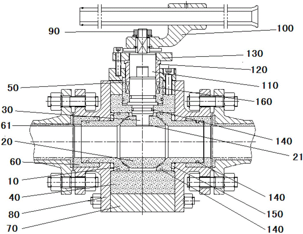
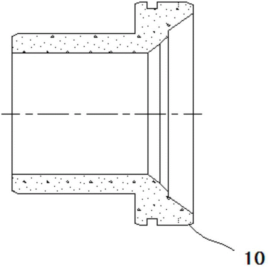
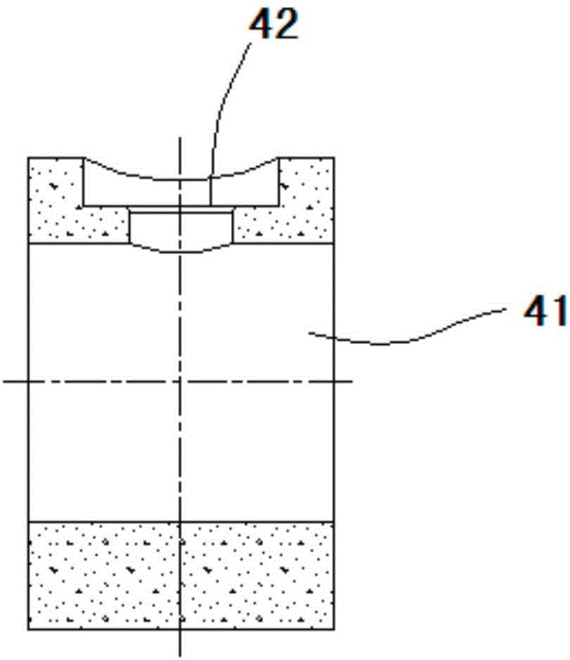
[0022] see Figure 1 to Figure 3 As shown, the present invention discloses a high-performance ceramic ball valve. The ceramic ball valve includes a valve seat 10 made of ceramics, a ball 20, a valve stem 30, a valve body bush 40, a stuffing box 50, a valve seat bush 60 and a metal material. The finished valve body 70, valve cover 80, fastener 90, handle seat 100, drive shaft 110, packing gland 120, packing pressure plate 130; the valve seat bushing 60 is provided with a stepped inner hole 61, and the stepped inner hole The outer diameter is connected with the inner hole of the valve cover 80, and the inner diameter of the stepped inner hole is connected with the outer circle of the tail of the valve seat 10. The joint is provided with multiple e...


PUM


Abstract

The invention discloses a high-performance ceramic ball valve. The ceramic ball valve comprises a valve seat, a ball body, a valve rod, a valve body lining, a packing box and a valve seat lining which are made of ceramic and a valve body, a valve deck, a fastening piece, a handle seat, a driving shaft, a packing pressing sleeve and a packing pressing plate which are made of metal materials; the valve seat lining is provided with a stepped inner hole, the outer diameter of the stepped inner hole is connected with an inner hole of the valve deck in a matched mode, the inner diameter of the stepped inner hole is connected with an outer circle located at the tail of the valve seat, and the joint of the stepped inner hole and the valve seat is provided with multiple elastic sealing rings. According to the high-performance ceramic ball valve, the structure is simple, multiple sealing structures are adopted, it is guaranteed that corrosive media cannot make contact with metal, and therefore serious potential safety hazards due to the fact that the metal materials are corroded by the media can be avoided.

Description

technical field [0001] The invention relates to a ball valve, in particular to a high-performance ceramic ball valve. Background technique [0002] The valves commonly used in various industries in China are metal valves. The use of metal valves has a history of hundreds of years. Although metal valves have been improved in structure and materials, they cannot adapt to the increasingly high wear and tear due to the limitations of metal material properties. Corrosion and other harsh working conditions are mainly reflected in the short service life and serious leakage, which greatly affect the stability of the system operation; traditional metal valves urgently need to be completely innovated in terms of materials, design and manufacturing processes; however, ceramic materials are due to their inherent It has excellent physical properties, such as excellent chemical corrosion resistance, wear resistance, high temperature resistance, and erosion resistance; therefore, ceramic b...

Claims


Application Information

Patent Timeline
IPC IPC(8): F16K5/06F16K5/08
CPCF16K5/06F16K5/0663F16K5/0694F16K5/08
Inventor 罗起飞戴文柏王邦捷卓桂朝
Owner SANBORA VALVE
Learn More