No-heat-exchange energy saving preparation device and method for preparing ammonia water from liquid ammonia directly
A technology for heat exchange, energy saving, and liquid ammonia, which is applied in chemical instruments and methods, mixing methods, transportation and packaging, etc. It can solve the problems of large statistical deviation of ammonia water flow, energy waste, ammonia water waste, etc., and achieve energy saving and reduction of energy consumption , the effect of improving efficiency
- Summary
- Abstract
- Description
- Claims
- Application Information
AI Technical Summary
Problems solved by technology
Method used
Image
Examples
Embodiment 1
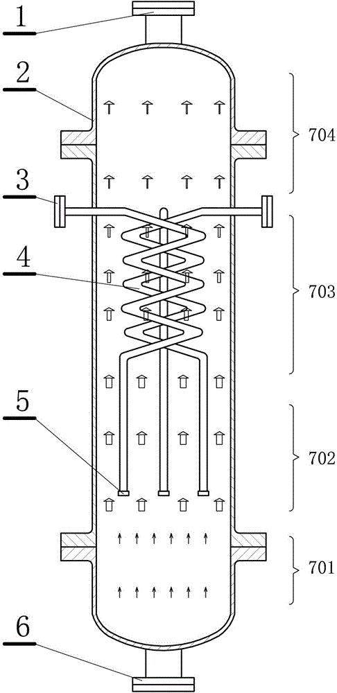
[0022] This embodiment is an energy-saving preparation device for directly producing ammonia from liquid ammonia without heat exchange, such as figure 1 shown. This embodiment includes: a cylindrical reaction tank 2, the bottom of the reaction tank is provided with a water inlet 6, the top of the reaction tank is provided with a dilute ammonia outlet 1, and the middle and upper part of the reaction tank is provided with multiple Liquid ammonia inlet 3, each of the liquid ammonia inlets is connected to its own coil 4, each of the coils is installed in a staggered manner, and extends to the middle and lower part of the reaction tank, and the coils are respectively connected to their respective distributors 5 connections.
[0023] The reaction tank can be cylindrical, that is, a body of revolution, or spherical or prismatic, similar to a vertical thick pipe with both ends closed. The cylindrical shape is a commonly used shape for chemical equipment, which is easy to process and...
Embodiment 2
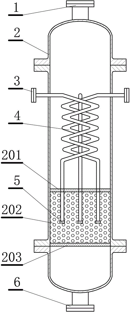
[0032] This embodiment is an improvement of the first embodiment, and is a refinement of the first embodiment about the reaction tank. The lower part of the reaction tank described in this embodiment is provided with two blocking nets 201, 203, and packing 202 is filled between the two blocking nets, and the packing surrounds each of the distributors, as figure 2 shown.
[0033] The filler is kept in a fixed position of the reaction tank by the bottom barrier net and the upper barrier net, and the barrier net can prevent the filler from spreading and maintain it around the distributor. The bottom barrier net is about one-sixth of the distance from the bottom of the reaction tank, the upper barrier net is about two-fifths of the distance from the bottom of the reaction tank, and the distributor is about one-fourth of the distance from the bottom of the reaction tank. between layers of barrier netting.
Embodiment 3
[0035] The improvement of the above-mentioned embodiment of this embodiment is the refinement of the above-mentioned embodiment regarding the coil. The coiled pipe described in this embodiment is bent in a zigzag shape.
[0036] The coiled pipe shape of the present embodiment is a zigzag distribution, or is called a serpentine distribution, such as figure 1 Shown is the state of three coiled pipes aligned with each other. The shape of the coil can be determined according to the requirements of the cost of the coil, the ease of manufacture and the demand for space and gasification.
PUM
 Abstract
Description
Claims
Application Information
 - R&D
- Intellectual Property
- Life Sciences
- Materials
- Tech Scout
- Unparalleled Data Quality
- Higher Quality Content
- 60% Fewer Hallucinations
Browse by: Latest US Patents, China's latest patents, Technical Efficacy Thesaurus, Application Domain, Technology Topic, Popular Technical Reports.
© 2025 PatSnap. All rights reserved.Legal|Privacy policy|Modern Slavery Act Transparency Statement|Sitemap|About US| Contact US: help@patsnap.com


