
Welding bogie

A bogie and frame technology, which is applied in the directions of bogies, railway car body parts, railway braking systems, etc., can solve the problems that the stability of the bogie cannot meet the requirements, the transmission efficiency of the braking system is reduced, and the transmission of braking force is uneven. , to achieve the effect of improving brake mitigation performance, improving dynamic performance, and meeting strength requirements

Inactive Publication Date: 2015-11-18
CRRC SHANDONG CO LTD
View PDF8 Cites 0 Cited by
  • Summary
  • Abstract
  • Description
  • Claims
  • Application Information

AI Technical Summary

Problems solved by technology

However, the traditional frame bogie has complex structure and various braking mechanisms, which brings many problems to production, operation and maintenance; at the same time, the transmission of braking force is uneven, and the wheels and rims are seriously worn.
[0003] The traditional freight car bogies are mostly three-frame structure, with large unsprung mass, lack of adaptability to the irregularity of the actual track, and poor anti-diamond deformation ability, resulting in the stability of the bogie can not meet the requirements; and in order to increase the anti-diamond stiffness, The structure usually adopted is relatively complicated, which will inevitably lead to an increase in manufacturing cost and also cause difficulties in maintenance.
At the same time, the layout of the basic braking device of the traditional bogie is relatively complicated, the braking performance is poor, the reliability of the relief is insufficient, and the transmission efficiency of the braking system is reduced

Method used


Image

  • Welding bogie
  • Welding bogie
  • Welding bogie

Examples


Embodiment Construction

[0025] The present invention will be further described below in conjunction with the accompanying drawings and embodiments.

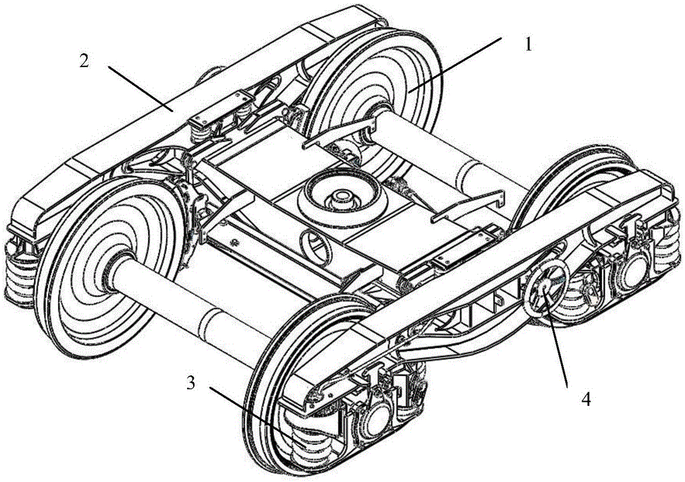
[0026] like figure 1 As shown, the new welded bogie includes a wheel set composition 1, a frame composition 2, an axle box suspension system 3, and a braking device 4.

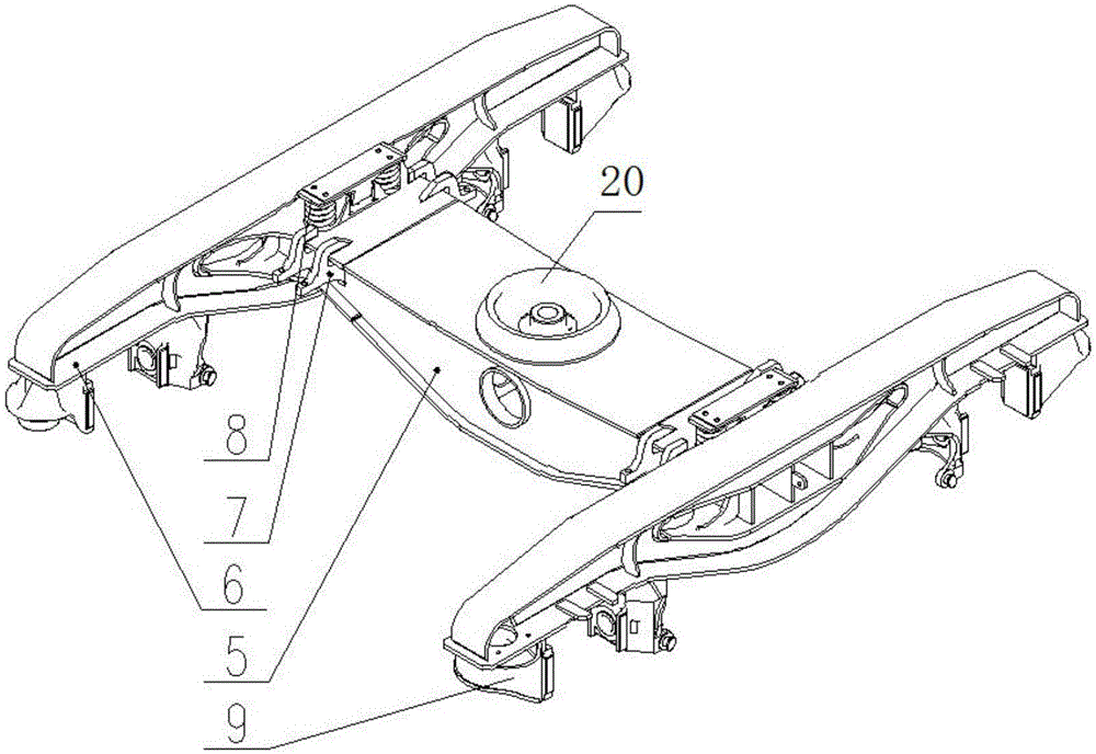
[0027] like figure 2 As shown, the frame composition 2 is formed by inserting the crossbeam 5 and two side beams 6, which meets the strength requirements and has a simple structure. The components 8 and the spherical center disk 20 on the beam 5 are connected with the vehicle body; the pedestal body 9 is connected with the axial suspension system 3 .

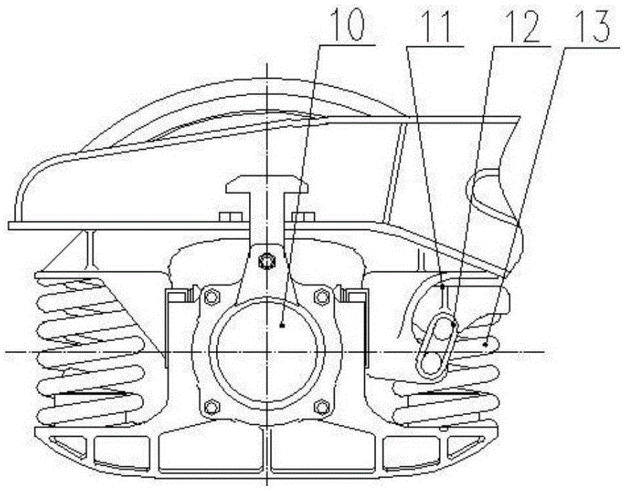
[0028] like image 3 As shown, the axle box suspension system 3 is a Linoer shock absorber structure, which is composed of an axle box component 10, a spring cap component 11, a suspension ring 12, a two-stage stiffness spring 13 and a top, which not only ensures the stability of linear operation, It also adapts to the passability of...


PUM


Abstract

The invention discloses a welding bogie. The welding bogie comprises wheel pair assemblies, a framework assembly, shaft box hanging systems and braking devices. The framework assembly is of an H-shaped structure formed by a beam and side beams in an inserting connection and installing and welding mode. The framework assembly is located on the two wheel pair assemblies through the shaft box hanging systems. Each braking device is an integrated foundation braking device. The integrated foundation braking devices are hung on the framework assembly through hanging rod assemblies. The framework assembly is formed by the beam and the side beams in the inserting connection and installing and welding mode. The requirement for strength is met, and the structure is simple. Linuoer shock absorber structures are adopted for the shaft box hanging systems, and therefore linear running stability is guaranteed, and the welding bogie adapts to curve passing capacity. Rubber springs are adopted for the shaft box hanging systems, and therefore the shaft box hanging systems have rigidity and damping in the vertical direction, the transverse direction and the longitudinal direction, the structure is simple, and maintaining is easy. The braking devices are the integrated foundation braking devices, and the best braking characteristic can be transmitted through the design principle of a parallelogram.

Description

technical field [0001] The invention relates to a novel welded bogie, which is suitable for railway wagons with a speed level of 120Km / h. Background technique [0002] At present, railway freight car bogies are generally divided into two types: frame type bogie and three-frame type bogie. The frame bogie has the advantages of light unsprung mass, small wheel-rail action force, and high critical speed. However, the traditional frame bogie has a complex frame structure and various braking mechanisms, which have brought many problems to production, operation, and maintenance; at the same time, the transmission of braking force is uneven, and the wheels and rims are seriously worn. [0003] The traditional freight car bogies are mostly three-frame structure, with large unsprung mass, lack of adaptability to the irregularity of the actual track, and poor anti-diamond deformation ability, resulting in the stability of the bogie can not meet the requirements; and in order to incre...

Claims


Application Information

Patent Timeline
Patent Type & Authority Applications(China)
IPC IPC(8): B61F3/00B61F5/30B61H11/00
Inventor 白文虽刘红日翟鹏军杨文朋
Owner CRRC SHANDONG CO LTD
Learn More