
Inner cavity drilled multi-cutter machining device

A processing device and cutting tool technology, which is applied in the field of multi-tool processing devices for inner cavity drilling, can solve the problems of low processing efficiency, low production efficiency, and processing of parts with porous drilling machines, so as to improve processing efficiency, improve processing efficiency, The effect of convenient clamping

Active Publication Date: 2015-11-18
ZHEJIANG UNIV
View PDF7 Cites 9 Cited by
  • Summary
  • Abstract
  • Description
  • Claims
  • Application Information

AI Technical Summary

Problems solved by technology

[0004] However, processing the inner cavity of the part, such as machining the hole for storing lubricant in the inner cavity of the oil-free bearing, etc., this kind of processing is still relatively cumbersome and the production efficiency is not high.
Generally, existing devices and methods can only process one hole at a time inside this type of part, and this type of part cannot be processed by a multi-hole drilling machine, so the processing efficiency is low

Method used


Image

  • Inner cavity drilled multi-cutter machining device
  • Inner cavity drilled multi-cutter machining device
  • Inner cavity drilled multi-cutter machining device

Examples


Embodiment Construction

[0034] The present invention will be further described below in conjunction with the accompanying drawings and specific embodiments.

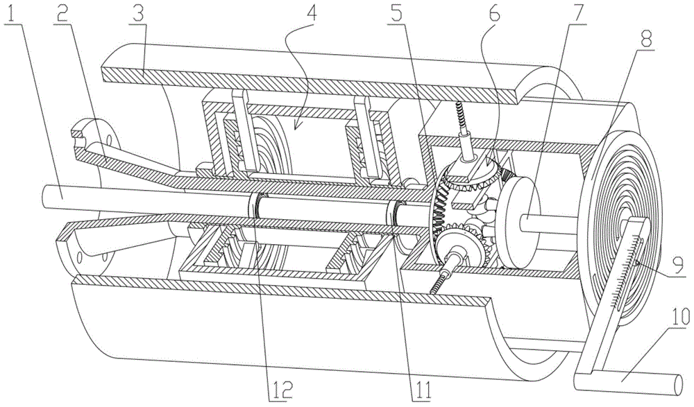
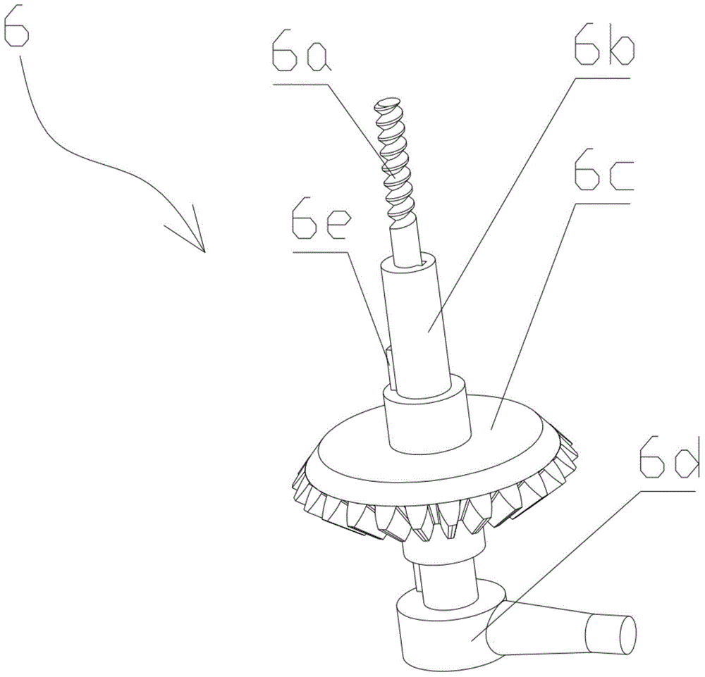
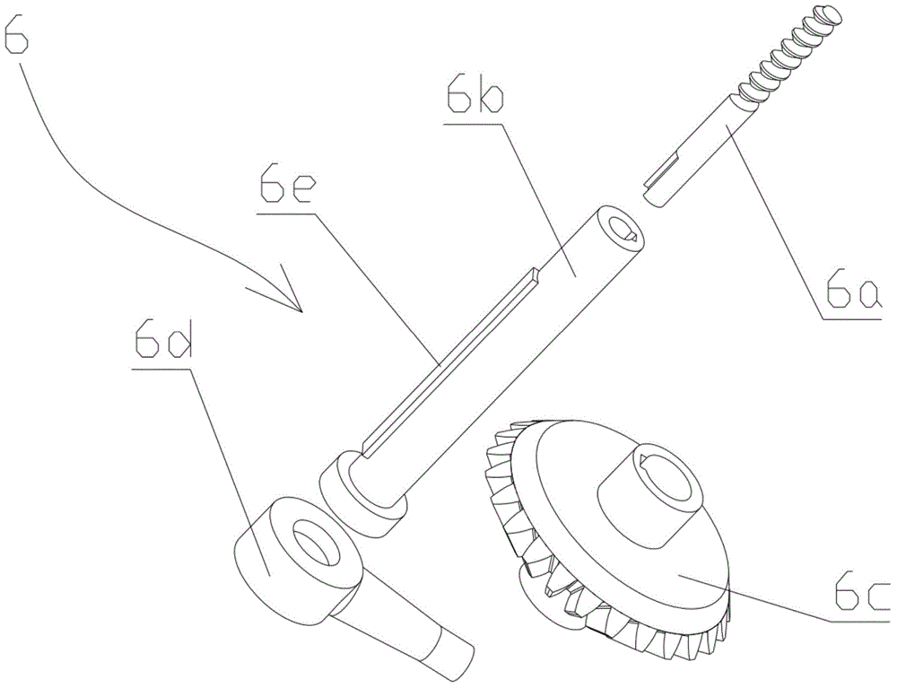
[0035] Such as figure 1 As shown, the present invention includes a tool mechanism 6, a transmission drive mechanism and a feed mechanism installed in the box body 2, and a support mechanism 4 that is connected between the outer wall of the box body 2 and the workpiece 3; the transmission drive mechanism connects the tool mechanism 6 to drive The tool rotates, and the feed mechanism is connected to the tool mechanism 6 to control its radial movement. The tool mechanism 6 includes multiple groups of tool assemblies uniformly distributed along the circumference, and each group of tool assemblies is radially installed and faces the inner wall of the workpiece 3, such as Figure 10 shown.

[0036] The transmission drive mechanism includes a main shaft 1 and a large bevel gear 5. The main shaft 1 is set in the central sleeve at one end of the box bo...


PUM


Abstract

The invention discloses an inner cavity drilled multi-cutter machining device. The device comprises a cutter mechanism, a transmission driving mechanism and a feeding mechanism mounted in a box, and a support mechanism connected between the outer wall of the box and a workpiece in a supporting manner, wherein the transmission driving mechanism is connected with the cutter mechanism to drive the cutters to rotate; the feeding mechanism is connected with the cutter mechanism, and controls the radial movement of the cutter mechanism; the cutter mechanism comprises multiple sets of cutter components uniformly distributed in the periphery; and each set of cutter components is mounted in the radial direction, and is arranged towards the inner wall of the workpiece. The device can synchronously machine multiple peripheral blind holes or through holes in the inner cavity of the part, needs no extra fixture in machining to achieve the clamping convenience, and can automatically and quickly center to greatly improve the machining efficiency.

Description

technical field [0001] The invention relates to a machine tool processing device, in particular to a multi-cutter processing device for inner cavity drilling. Background technique [0002] The machine tool industry is the basic equipment industry of the national economy and the top priority for the development of the equipment manufacturing industry. With the continuous, rapid and steady growth of the national economy, my country's machine tool industry has made considerable development and progress. [0003] Oil-free bearings have the characteristics of high load capacity, impact resistance, high temperature resistance, and strong self-lubricating ability. They are especially suitable for occasions where it is difficult to lubricate and form an oil film such as heavy loads, low speeds, reciprocating or swinging, and have been widely used in metallurgical continuous casting machines, Steel rolling equipment, mining machinery, ships, steam turbines, water turbines, injection...

Claims


Application Information

Patent Timeline
Patent Type & Authority Applications(China)
IPC IPC(8): B23B43/00B23B47/04B23B47/18B23Q3/12
CPCB23B43/00B23Q3/12B23Q5/04B23Q5/22
Inventor 张树有朱国文
Owner ZHEJIANG UNIV
Learn More