
Fired mold precision casting method for improving solidification heat dissipation conditions of directional solidification casting

A technology of investment precision casting and directional solidification, which is applied in the direction of casting molding equipment, casting molds, casting mold components, etc., can solve the problem of optimization of the structure and performance of castings with high temperature gradients that cannot guarantee the solidification interface of castings, and cannot fundamentally improve castings. Solidification interface temperature gradient, poor thermal conductivity of mold shell materials, etc.

Active Publication Date: 2015-11-11
BEIJING BEIYE FUNCTIONAL MATERIALS CORP
View PDF5 Cites 2 Cited by
  • Summary
  • Abstract
  • Description
  • Claims
  • Application Information

AI Technical Summary

Problems solved by technology

[0004] Generally speaking, the interface heat transfer coefficient h between the casting and the chilled plate C Larger, about 1500W / (m 2 k) or so, while the other three items have poor thermal conductivity due to the shell material, the heat transfer coefficient h gap 、h sheel 、h r than h C An order of magnitude smaller, resulting in the total heat transfer coefficient H of the casting and the environment b Very low, unable to guarantee the high temperature gradient of the solidification interface of the casting and the optimization of the microstructure and properties of the casting
At present, the Bridgman method, LMC method, GCC and FBQ method that have been researched and developed in the world all only improve the conditions for heat dissipation from the surface of the mold shell to the surrounding environment, and do not fundamentally change the huge thermal resistance brought by the mold shell itself during the solidification process of the casting. Therefore, it is impossible to fundamentally improve the temperature gradient at the solidification interface of the casting.

Method used


Image

  • Fired mold precision casting method for improving solidification heat dissipation conditions of directional solidification casting
  • Fired mold precision casting method for improving solidification heat dissipation conditions of directional solidification casting
  • Fired mold precision casting method for improving solidification heat dissipation conditions of directional solidification casting

Examples


Embodiment 1

[0020] Embodiment 1, the improvement of the current directional solidification method only improves the condition of heat dissipation from the surface of the mold shell to the surrounding environment, and does not fundamentally change the huge thermal resistance brought by the mold shell itself during the solidification process of the casting, so it is difficult to fundamentally improve the quality of the casting. The temperature gradient at the solidification interface. For this reason, this embodiment adopts an investment casting method that improves the solidification and heat dissipation conditions of directional solidification castings, and the specific steps are as follows:

[0021] Step 1: Prepare a wax mold of the specifications required by the casting according to the conventional method, and manufacture the inner cavity of the mold shell.

[0022] Step 2: Make the surface layer and the back layer of the formwork according to material requirements.

[0023] Step 3: P...

Embodiment 2

[0027] Embodiment 2, the specific steps of this embodiment are as follows:

[0028] Step 1: Prepare a wax mold of the specifications required by the casting according to the conventional method, and manufacture the inner cavity of the mold shell.

[0029] Step 2: Make the surface layer and the back layer of the formwork according to material requirements.

[0030] Step 3: Prepare equidistant rectangular grooves with an interval of 8 mm on the outer surface of the formwork, and then perform firing strengthening.

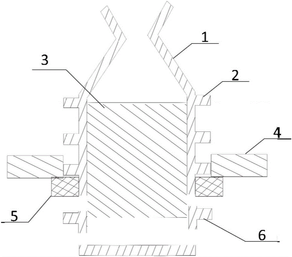
[0031] Step 4: Install a mechanical expansion device that matches the equidistant rectangular groove in step 3 immediately below the heat shield of the directional solidification furnace, that is, the mechanical expansion device can be embedded in the equidistant rectangular groove.

[0032] Step 5: Install the qualified groove-shaped formwork into the directional solidification furnace, pour alloy liquid into the formwork, and move the formwork to the bottom of the ...


PUM


Abstract

The invention belongs to the technical field of precision casting of directional solidification column crystal or single crystal test bars, and relates to a fired mold precision casting method for improving solidification heat dissipation conditions of a directional solidification casting. In the directional column crystal or single crystal test bar manufacturing process, selected mold shell materials are the same as universal mold shell materials. The shape of a mold shell is changed, the equal-distance variable cross section is increased, and a plurality of equal-distance rectangular grooves are formed. When the directional solidification test bars and the mold shell move to the position below a heat insulation plate together, mechanical expansion rings arranged in a directional solidification furnace are inlaid in the equal-distance rectangular grooves of the mold shell; the mechanical expansion rings expand downwards to remove the part, below the grooves, of the mold shell; the lower end of the directional solidification casting is in direct contact with cooling media, so that the heat exchange conditions of the directional solidification test bars and the cooling media are improved; and therefore, the cooling speed of the directional solidification casting and the temperature gradient of a solid-liquid interface are greatly improved, the dendritic crystal structure of the directional solidification casting is refined, dendritic segregation is reduced, and the mechanical property of the casting is remarkably improved.

Description

technical field [0001] The invention belongs to the technical field of precision casting of directional solidification castings, and in particular provides an investment precision casting method for improving directional solidification heat dissipation conditions. Background technique [0002] In the casting process of directional solidification castings, the precision mold shell casting method is commonly used at present. The heat exchange between the casting and the environment has four control links, which are: the interface heat transfer between the casting and the chilled plate (heat transfer coefficient h C ); the radiation heat transfer between the casting and the inner surface of the mold shell (heat transfer coefficient h gap ); heat conduction through the formwork (heat conduction coefficient h sheel ); the heat transfer between the shell and the ambient cooling medium (heat transfer coefficient h r ). The total heat transfer coefficient between the casting and...

Claims


Application Information

Patent Timeline
IPC IPC(8): B22C9/04B22D27/04
Inventor 李振瑞安宁徐静玉
Owner BEIJING BEIYE FUNCTIONAL MATERIALS CORP
Learn More