A high-power array ultrathin electrode oxygen-metal battery
A metal battery and array technology, applied in hybrid batteries, fuel cell half-cells, primary battery half-cells, circuits, etc., can solve the problems of rare raw materials, unfriendly environment, and high dependence on infrastructure, and achieve material Accessible, material-rich effects
- Summary
- Abstract
- Description
- Claims
- Application Information
AI Technical Summary
Problems solved by technology
Method used
Image
Examples
Embodiment 1
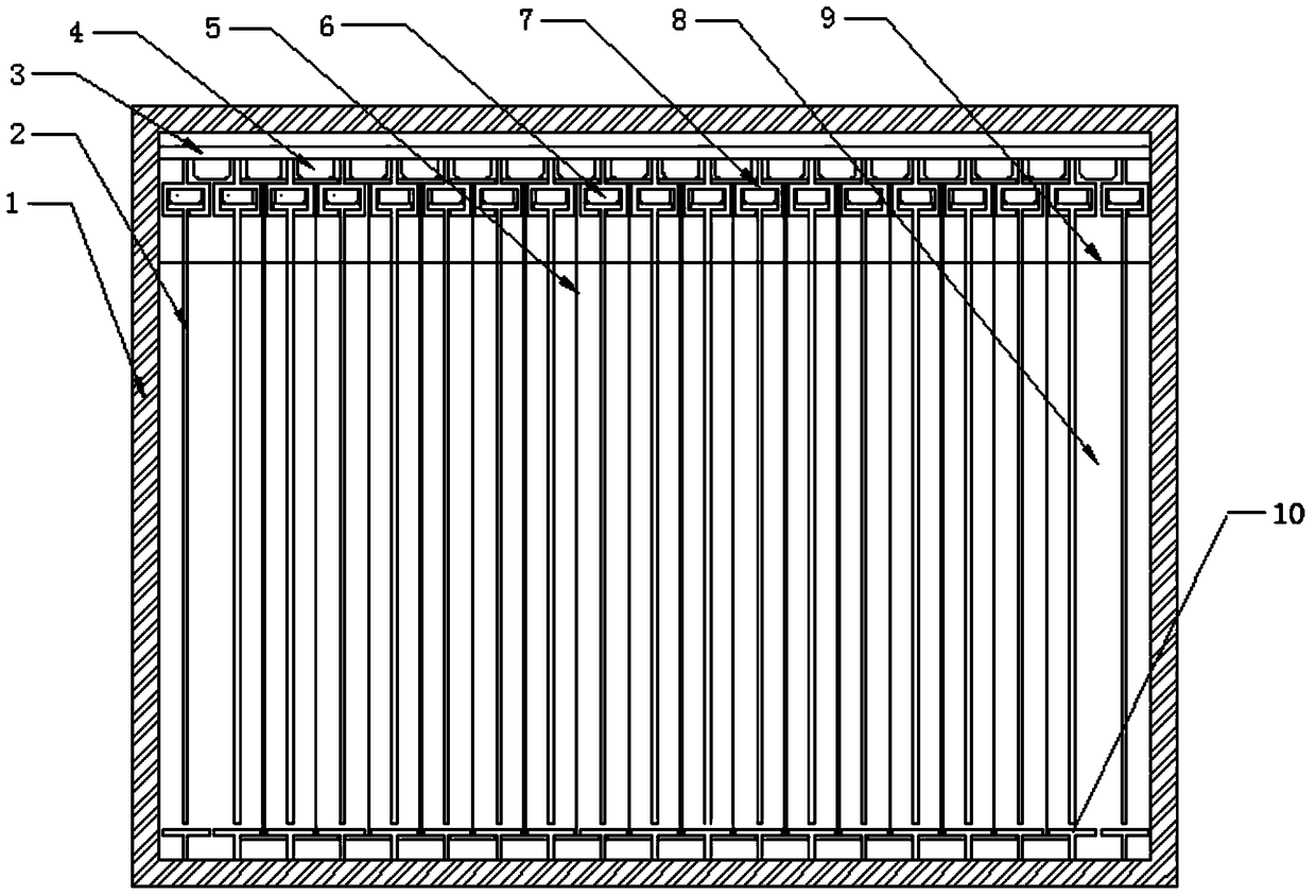
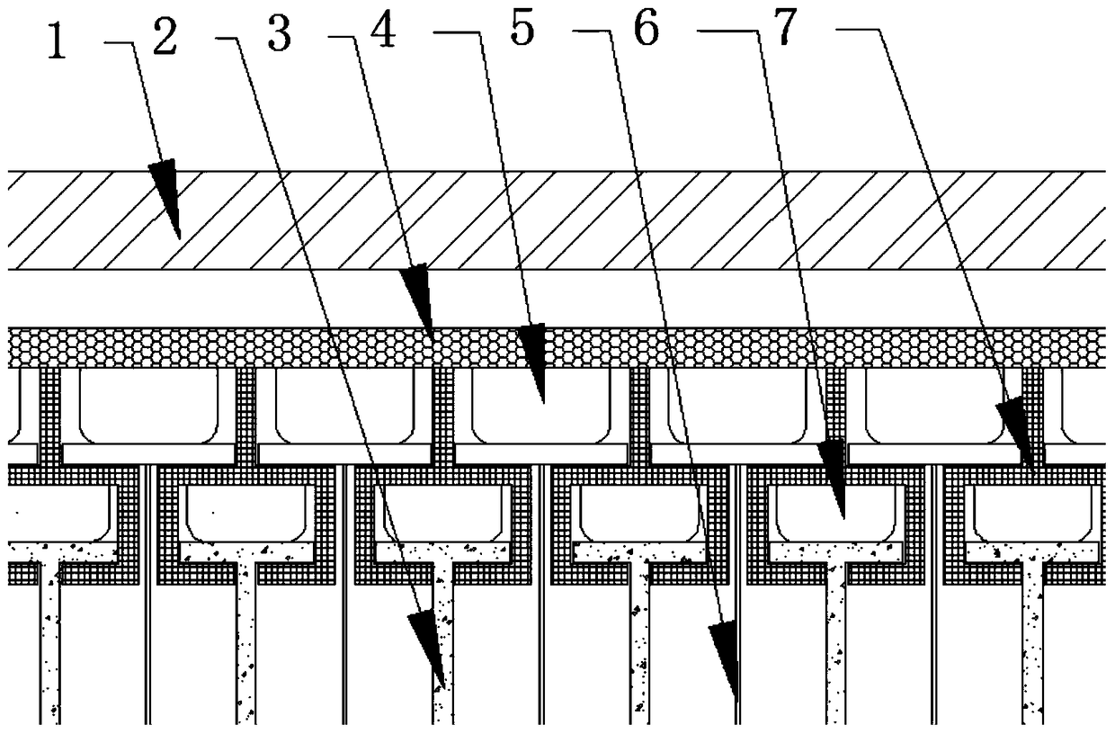
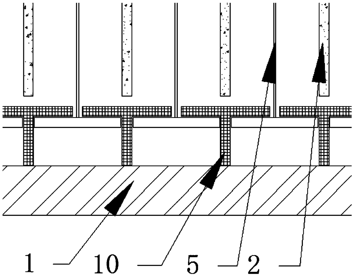
[0027] The battery casing 1 is a battery container, and there is a mounting plate 3 near the upper part. The mounting plate 3 is equipped with elongated slots with a cross-section in the shape of the electrode slot 7, and an anode buckle 4 is installed between the electrode slots 7 on the mounting plate 3. , the cathode buckle 6 is installed inside the electrode slot 7, and the T-shaped anode lower slot 10 is installed on the bottom plate of the battery case 1. When in use, insert the two ends of the 0.01mm thick aluminum foil ultra-thin anode 5 into the electrode slot 7 and the anode Form an array on the lower card slot 10, tension it, the distance between the centers of the adjacent aluminum foil ultra-thin anodes 5 is 2 mm, and at the same time insert the 1 mm thick graphite ultra-thin cathode 2 into the electrode card slot 7, and the center distance between the adjacent graphite ultra-thin cathodes 2 is 2 mm , the internal space is 100 pairs of electrodes in the battery cas...
Embodiment 2
[0029] The battery casing 1 is a battery container, and there is a mounting plate 3 near the upper part. The mounting plate 3 is equipped with elongated slots with a cross-section in the shape of the electrode slot 7, and an anode buckle 4 is installed between the electrode slots 7 on the mounting plate 3. , the cathode buckle 6 is installed inside the electrode slot 7, and the T-shaped anode lower slot 10 is installed on the bottom plate of the battery case 1. When in use, insert the two ends of the 0.05mm thick zinc foil ultra-thin anode 5 into the electrode slot 7 and An array is formed on the lower anode slot 10, tensioned, the distance between the centers of the adjacent zinc foil ultra-thin anodes 5 is 2mm, and a 1mm thick graphite ultra-thin cathode 2 is inserted into the electrode slot 7, and the centers of the adjacent graphite ultra-thin cathodes 2 are There are 100 pairs of electrodes in the battery casing 1 with an interval of 2 mm and an internal space of 20 cm. In...
Embodiment 3
[0031] The battery casing 1 is a battery container, and there is a mounting plate 3 near the upper part. The mounting plate 3 is equipped with elongated slots with a cross-section in the shape of the electrode slot 7, and an anode buckle 4 is installed between the electrode slots 7 on the mounting plate 3. , the cathode buckle 6 is installed inside the electrode card slot 7, and the T-shaped anode lower card slot 10 is installed on the bottom plate of the battery case 1, and the 0.04mm thick Mg 66 Zn 30 Ca 4 The two ends of the ultra-thin anode 5 of the amorphous alloy strip are inserted into the electrode slot 7 and the anode lower slot 10 to form an array, tensioned, adjacent to Mg 66 Zn 30 Ca 4 The ultra-thin anodes 5 have a center interval of 2 mm, and at the same time insert the 1 mm thick graphite ultra-thin cathode 2 into the electrode slot 7, the adjacent graphite ultra-thin cathodes 2 have a center interval of 2 mm, and the internal space is 100 pairs of electrodes...
PUM
| Property | Measurement | Unit |
|---|---|---|
| specific surface area | aaaaa | aaaaa |
| specific surface area | aaaaa | aaaaa |
| specific surface area | aaaaa | aaaaa |
Abstract
Description
Claims
Application Information
 - Generate Ideas
- Intellectual Property
- Life Sciences
- Materials
- Tech Scout
- Unparalleled Data Quality
- Higher Quality Content
- 60% Fewer Hallucinations
Browse by: Latest US Patents, China's latest patents, Technical Efficacy Thesaurus, Application Domain, Technology Topic, Popular Technical Reports.
© 2025 PatSnap. All rights reserved.Legal|Privacy policy|Modern Slavery Act Transparency Statement|Sitemap|About US| Contact US: help@patsnap.com


