
An artificial magnetic conductor unit, an artificial magnetic conductor structure and a planar antenna

A technology of artificial magnetic conductor and planar antenna, applied in the direction of radiating element structure, antenna, antenna grounding switch structure connection, etc., can solve the bottleneck of narrow-band characteristics and other problems, and achieve the effect of wide application range

Active Publication Date: 2018-10-30
SOUTH CHINA UNIV OF TECH
View PDF4 Cites 0 Cited by
  • Summary
  • Abstract
  • Description
  • Claims
  • Application Information

AI Technical Summary

Problems solved by technology

At present, there are many studies on artificial magnetic conductors, but their narrow-band characteristics have always been the bottleneck in the study of artificial magnetic conductors.

Method used


Image

  • An artificial magnetic conductor unit, an artificial magnetic conductor structure and a planar antenna
  • An artificial magnetic conductor unit, an artificial magnetic conductor structure and a planar antenna
  • An artificial magnetic conductor unit, an artificial magnetic conductor structure and a planar antenna

Examples


Embodiment

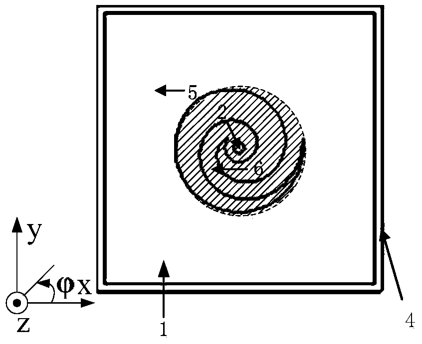
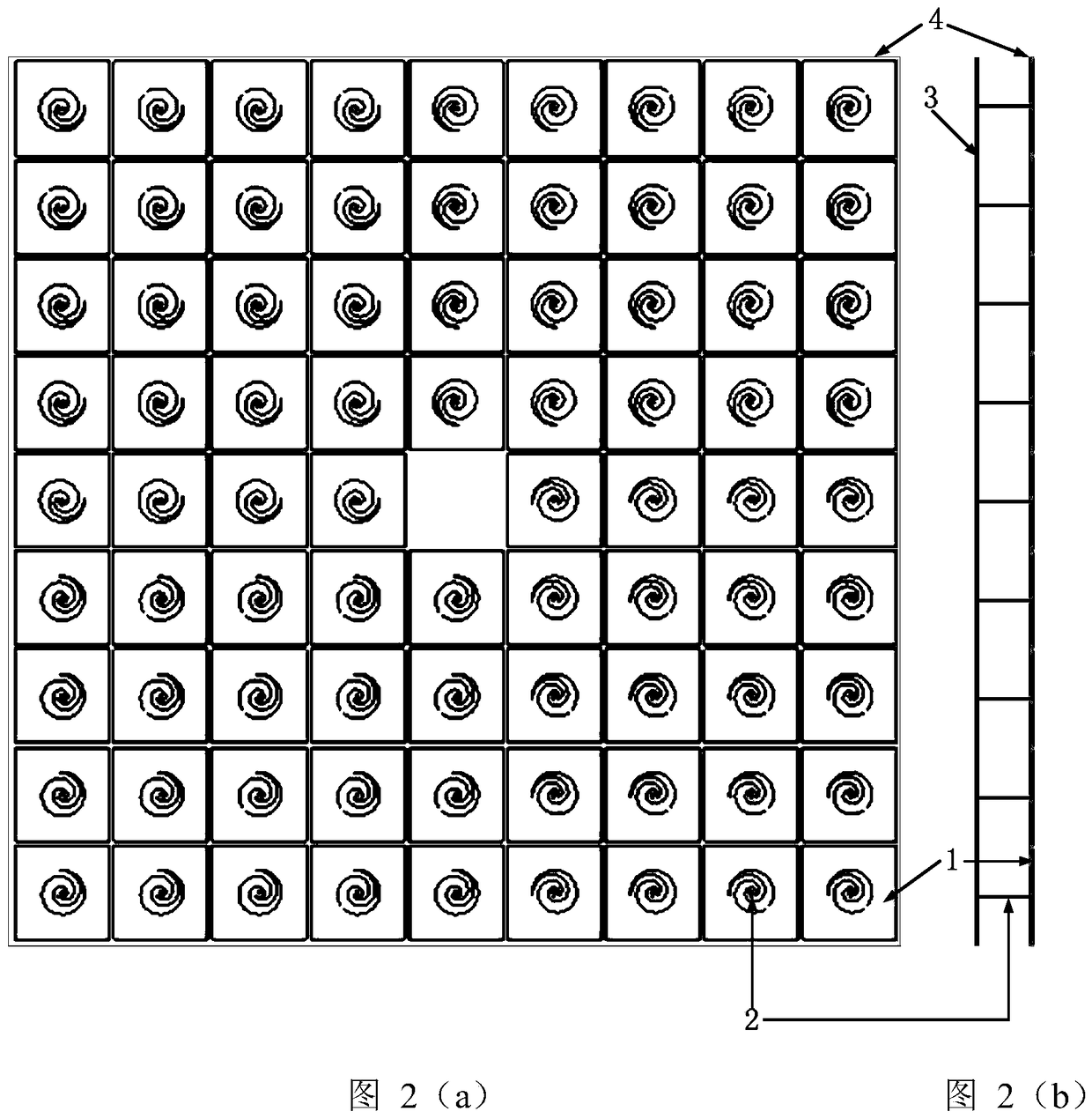
[0030] Such as Figure 1(a)-Figure 1(b) As shown, an artificial magnetic conductor unit includes a metal periodic patch 1, a metal via hole 2, a metal ground plate 3 and a dielectric substrate 4, and the metal periodic patch 1 consists of a square patch 5 hollowed out in the center and a spiral wire 6, the helix 6 is set in the hollowed out part of the square patch 5 and connected to the square patch 5, the helix 6 is electrically connected to the metal ground plate 3 through the metal via hole 2, and the metal period The patch 1 is etched on the dielectric substrate. The metal via hole 2 forms an LC parallel equivalent circuit between the metal periodic patch 1 and the metal ground plate 3, wherein the square patch 5 of the metal periodic patch 1 can be equivalent to a capacitor, and the spiral 6 can be equivalent to an inductor , and the metal via 2 can be equivalent to an inductor. This structure can effectively expand the bandwidth. The diagonal part shown in Fig. 1(a) ...


PUM

PropertyMeasurementUnit
Radiusaaaaaaaaaa

Abstract

The present invention discloses an artificial magnetic conductor unit, an artificial magnetic conductor structure and a planar antenna. The artificial magnetic conductor unit comprises a metal periodic patch, a metal via hole, a metal ground plate and a dielectric substrate, wherein the metal periodic patch consists of a square patch with a hollowed center and a spiral line, the spiral line is arranged at the hollowed center part of the square patch and is connected with the square patch, the spiral line is connected with the metal ground plate through the metal via hole, and the metal periodic patch is etched on the dielectric substrate. The artificial magnetic conductor structure comprises the plurality of artificial magnetic conductor units which are distributed periodically, and the planar antenna comprises an antenna oscillator and the artificial magnetic conductor structure arranged below the antenna oscillator. As the artificial magnetic conductor structure is used as a planar base station antenna reflecting plate, the height of the antenna can be reduced to 1 / 3 of the original height of the antenna, and the artificial magnetic conductor structure is simultaneously adapted to a plurality of polarized antennas, thus wide application range is achieved.

Description

technical field [0001] The invention relates to the field of metamaterials for electromagnetic fields, in particular to an artificial magnetic conductor unit, an artificial magnetic conductor structure and a planar antenna. Background technique [0002] In recent years, more and more terms such as soft and hard surfaces, electromagnetic bandgap structures, left-handed materials, and artificial magnetic conductors (Artificial Magnetic Conductor, AMC) have appeared in the field of electromagnetic field technology. These structures or materials have properties that do not exist in nature. Existing but extremely valuable electromagnetic properties, so these structures or materials are also called metamaterials, and their peculiar electromagnetic properties have shown strong advantages in the field of realizing new high-performance antennas and microwave devices. [0003] Since the surface of a Perfect Electronic Conductor (PEC) needs to satisfy the boundary condition: the tangen...

Claims


Application Information

Patent Timeline
IPC IPC(8): H01Q1/38H01Q1/50H01Q15/24
Inventor 李融林李伏云崔悦慧
Owner SOUTH CHINA UNIV OF TECH
Learn More