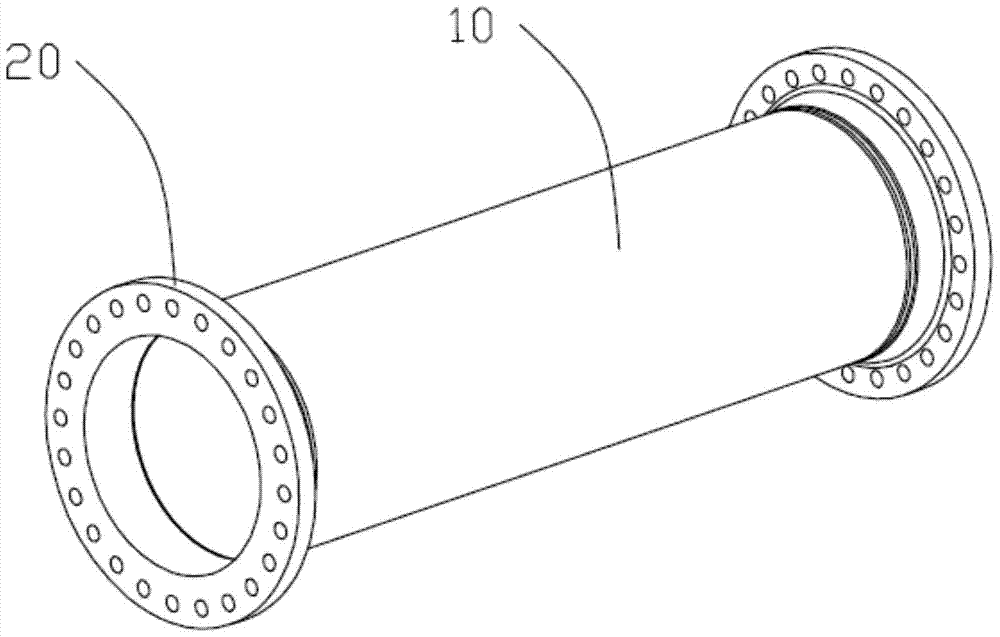
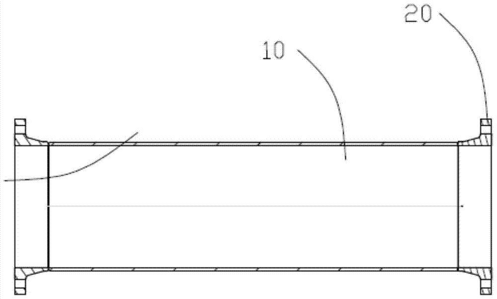
Improved butt submerged arc welding method of steel pipe and flange with neck
A submerged arc welding and flange technology, which is applied in welding equipment, arc welding equipment, workpiece edge, etc., can solve the problems of affecting welding quality, easy to be affected by moisture and oxidation, and slow welding speed, so as to increase welding speed and improve work environment, the effect of reducing the amount of filling
- Summary
- Abstract
- Description
- Claims
- Application Information
AI Technical Summary
Problems solved by technology
Method used
Image

Examples
experiment example 1
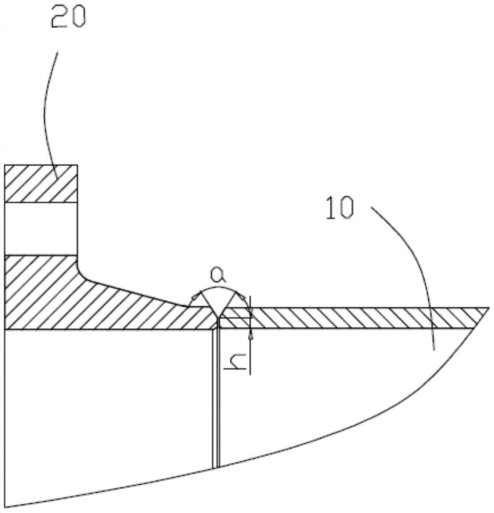
[0024] Experimental example 1, the influence of the distance between the end faces of welded joints on the welding effect.
[0025] At the time of the invention, weldments with a thickness of 8 to 24 mm were selected, and the distances between the welding end faces were set to 0, 0.5, 1.0, 1.5, 2.0, 2.5, 3.0, 3.5, and 4.0 mm, and conventional welding conditions were used for welding. The results showed that: When the distance between the end faces of the welded joint is less than 1 mm, the high current will not burn through the weldment, and the strength and toughness of the weld metal are the best.
experiment example 2
[0026] Experimental example 2, the influence of welding current, arc voltage and welding speed on welding effect
[0027] At the time of the invention, weldments with a thickness of 8-24mm were selected, and the welding wire was 3.2-5mm in diameter. Different welding currents, arc voltages and welding speeds were used for welding. The results showed that the welding current was 510-900A, and the arc voltage was 29-36V. When the welding speed is 32-60cm / min, the zigzag shape of the cross-section of the weldment joint obtained is better;
experiment example 3
[0028] Experimental example 3, the influence of the centerline distance of the displacement tube of the inner and outer welding torches on the weld formation
[0029] The diameter of the pipe selected at the time of invention is For the weldment, using the welding parameters in Experimental Example 2, the inner and outer welding torches are displaced at different distances during welding. The results show that when the pipe diameter is greater than or equal to 325mm and less than or equal to 1016mm, the displacement of the inner (outer) welding torch is 15-75mm ( When the pipe diameter increases and the displacement distance also increases) and is welded in an up (down) slope state, the appearance of the weld is flat and uniform, and can meet the first-class requirements for the appearance quality of the weld;
PUM
| Property | Measurement | Unit |
|---|---|---|
| length | aaaaa | aaaaa |
| thickness | aaaaa | aaaaa |
| diameter | aaaaa | aaaaa |
Abstract
Description
Claims
Application Information
 - R&D
- Intellectual Property
- Life Sciences
- Materials
- Tech Scout
- Unparalleled Data Quality
- Higher Quality Content
- 60% Fewer Hallucinations
Browse by: Latest US Patents, China's latest patents, Technical Efficacy Thesaurus, Application Domain, Technology Topic, Popular Technical Reports.
© 2025 PatSnap. All rights reserved.Legal|Privacy policy|Modern Slavery Act Transparency Statement|Sitemap|About US| Contact US: help@patsnap.com