Hydraulic plate bending machine

A technology of bending machine and hydraulic plate, applied in the field of hydraulic sheet metal bending machine, can solve the problems of low machining accuracy, and achieve the effects of reasonable structure design, improved mechanization degree and high transmission accuracy

Active Publication Date: 2015-10-21
安徽中瑞机床制造有限公司
View PDF9 Cites 8 Cited by
  • Summary
  • Abstract
  • Description
  • Claims
  • Application Information

AI Technical Summary

Problems solved by technology

[0007] The purpose of the present invention is to overcome the problem of low processing accuracy of the bending machine in the prior art, and to provide a hydraulic sheet metal bending machine. The technical solution of the present invention can greatly improve the bending accuracy of the bending machine. bending accuracy, and improve work efficiency

Method used


Image

  • Hydraulic plate bending machine
  • Hydraulic plate bending machine
  • Hydraulic plate bending machine

Examples


Embodiment 1

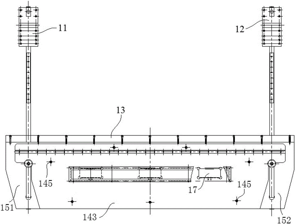
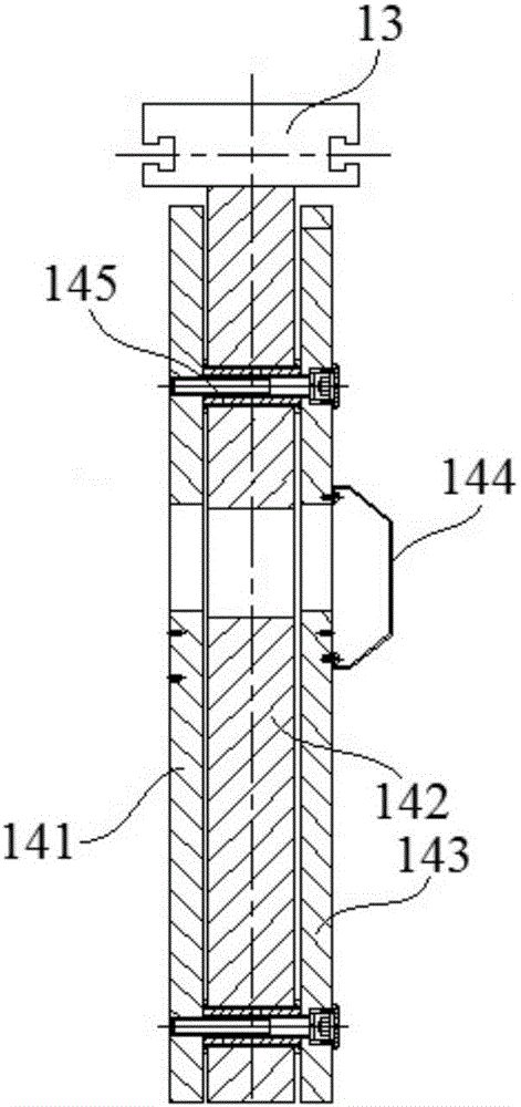
[0042] combine figure 1 , figure 2 , image 3 , Figure 4 , Figure 5 , Figure 6 , Figure 7 , Figure 8 , Figure 9 , Figure 10 and Figure 11 , a hydraulic sheet metal bending machine in this embodiment includes a frame, a slider assembly, a slider stroke adjustment mechanism, a synchronization mechanism and a backgauge mechanism.

[0043] Such as figure 1 , figure 2 and image 3 As shown, the frame in this embodiment includes a first wallboard 11, a second wallboard 12, a workbench panel 13, a rear vertical board 141, a main vertical board 142, a front vertical board 143, a casing 144, and locking pins 145. The first side vertical plate 151, the second side vertical plate 152, the anchor bolts 16 and the compensation cylinder 17, wherein: the rear vertical plate 141 and the front vertical plate 143 are vertically arranged in parallel, and the rear vertical plate 141 and the A main vertical board 142 is installed between the front vertical boards 143, a work...


PUM

PropertyMeasurementUnit
lengthaaaaaaaaaa
diameteraaaaaaaaaa
heightaaaaaaaaaa

Abstract

The invention discloses a high-precision hydraulic plate bending machine and belongs to the technical field of machine tool manufacturing. The high-precision hydraulic plate bending machine comprises a frame, a slider assembly, a slider travel adjustment mechanism, a synchronous mechanism, and a rear stop mechanism. The middle of each of rear, main and front vertical plates of the frame is provided with a cylinder holding cavity which three compensating cylinders are mounted inside. The lower portion of a slider is connected with an upper die through a clamping component. The upper die is composed of twenty upper die segments. In the slider travel adjustment mechanism, a first worm and a second worm are driven through a transmission shaft so as to drive a first screw and a second screw to adjust up and down; two synchronous forks are fixedly connected to a synchronous shaft of the synchronous mechanism, and the moving ends of the synchronous forks are both connected with the slider through a fork joint bearing. The rear stop mechanism comprises a transmission system component and a slide carriage system component. The high-precision hydraulic plate bending machine has the advantages that precision of the machine bending work pieces is greatly improved and work efficiency of workers is also improved.

Description

[0001] The patent application of the present invention is a divisional application with application number: 2013107546125. The application date of the original application is: 2013 / 12 / 31. The name of the invention is: a high-precision hydraulic sheet metal bending machine. technical field [0002] The invention relates to the technical field of machine tool manufacturing, and more specifically relates to a hydraulic plate bending machine. Background technique [0003] Bending machine products are widely used in: electromechanical, sheet metal, light industry, aviation, shipbuilding, instrumentation, electrical appliances, stainless steel products, steel structure construction and metallurgical industries, etc., used to cut various steel plates, stainless steel, copper plates, aluminum plates and non-woven fabrics Metal material sheet, which can fold the product into V-shaped, arc-shaped, round or right-angled, etc., and can also be designed and processed into special shape mo...

Claims


Application Information

Patent Timeline
Patent Type & Authority Applications(China)
IPC IPC(8): B21D5/06
CPCB21D5/06C22C38/005C22C38/008C22C38/02C22C38/04C22C38/12C22C38/16C22C38/60
Inventor 夏业春夏尧林
Owner 安徽中瑞机床制造有限公司
Why Eureka
Try Eureka