
Cabinet cooing system for servers of cloud computing computer room

A technology for server cabinets and computer rooms, which is applied in the direction of cooling/ventilation/heating transformation, temperature control using electric methods, etc. It can solve problems such as increasing the cooling effect of air conditioners, abnormal operation of network systems, overheating of server equipment, etc., and achieve local solutions Effects of overheating and hot spots, faster circulation, and higher efficiency

Active Publication Date: 2015-09-16
CHINA TOBACCO ZHEJIANG IND
View PDF10 Cites 17 Cited by
  • Summary
  • Abstract
  • Description
  • Claims
  • Application Information

AI Technical Summary

Problems solved by technology

[0003] There are multiple server devices placed in the existing cabinet, and these server devices will generate a lot of heat during operation. If the temperature cannot be cooled in a timely and effective manner, the accumulated heat will easily cause the server devices to overheat and crash, resulting in network system failure. abnormal
At present, the temperature inside the cabinet is mainly lowered by air conditioning, but in this cooling method, the cold air conditioned by the air conditioner flows disorderly inside the cabinet, and uneven cooling is likely to occur; in order to ensure that the equipment is Running at normal temperature will inevitably increase the cooling effect of the air conditioner, so as to ensure that the temperature inside the cabinet is in a normal state, but the energy consumption of the air conditioner will also increase accordingly, which is not conducive to energy conservation and environmental protection

Method used


Image

  • Cabinet cooing system for servers of cloud computing computer room
  • Cabinet cooing system for servers of cloud computing computer room
  • Cabinet cooing system for servers of cloud computing computer room

Examples


Embodiment Construction

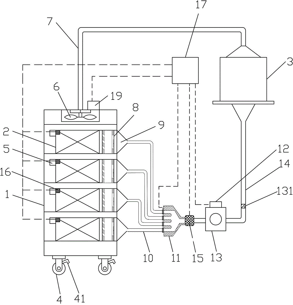
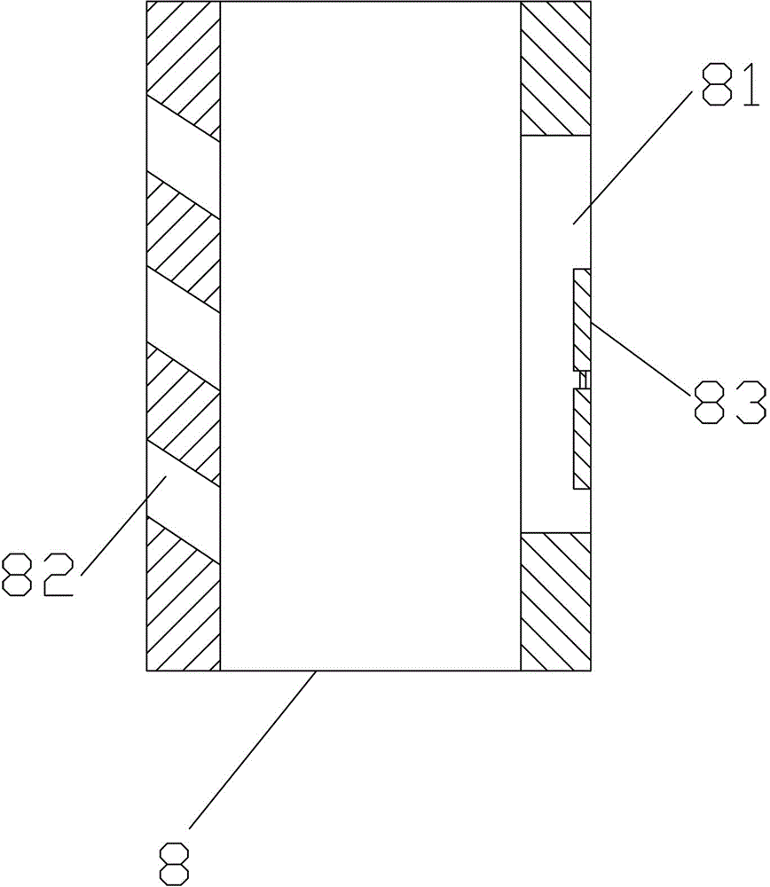
[0024] See attached picture. This embodiment includes a closed cabinet 1, in which a plurality of server cabinets 2 are placed from top to bottom; one side of the server cabinet is provided with a hot air discharge pipe 5, and the other side is provided with a cold air box 8; The rollers 4 facilitate the movement and transportation of the cabinet. The universal rollers are equipped with a brake device 41 to ensure reliable installation of the cabinet. A hot air fan 6 is arranged above the cabinet. 7 is communicated with the inlet of air conditioner 3.

[0025] In the present embodiment, the cold air outlet of air conditioner 3 is connected with the cold air duct 14; the one-way centrifugal fan 13 is arranged on the inlet end of the cold air duct, and the connection between the cold air duct and the one-way centrifugal fan is a detachable connection; the one-way centrifugal fan 13 imports At least one annular groove 132 is provided on the outer wall of the end, and a rubber st...


PUM


Abstract

The present invention discloses a cabinet cooling system for servers of a cloud computing computer room. The cabinet cooling system comprises a closed cabinet; the cabinet is used for placing server chassis; Hot air exhaust pipes are arranged at one sides of the server chassis and cold air boxes are arranged at the other sides of the server chassis; an air conditioning cold wind outlet is connected with a cold wind flow pipeline; the cold wind flow pipeline is connected with a plurality of cold wind conveying pipes by a cold wind flow dividing apparatus; the cold wind conveying pipes are connected with the cold air boxes; electromagnetic control valves are arranged on all the cold wind conveying pipes; a unidirectional centrifugal fan is arranged on the cold wind flow pipelines; a wind inlet frequency converter is mounted on the unidirectional centrifugal fan; a hot air fan is arranged at the upper part of the cabinet; a wind outlet frequency converter is arranged on the hot air fan; and the signal input ends of the wind inlet frequency converter, the wind outlet frequency converter and the electromagnetic control valves are all connected with a controller. The cabinet cooing system has a simple structure, is convenient and rapid to mount, efficiently solves the problems of overheated local parts and hot spots of the servers, has good radiating and cooling effects and ensures safety and reliability of operation of the servers.

Description

technical field [0001] The invention relates to a computer room temperature adjustment system, in particular to a server cabinet cooling system in a cloud computer room. Background technique [0002] Cloud computing is an Internet-based computing method in which shared hardware and software resources and information can be provided to computers and other devices on demand. Cloud computing is the growth, usage and delivery model of Internet-based related services, usually involving the provision of dynamically scalable and often virtualized resources over the Internet. The computer room of the cloud computing data center is an indispensable and important component in providing cloud computing data services, and the cabinet can protect the stored server equipment, shield electromagnetic interference, and arrange the equipment in an orderly and neat manner to facilitate future maintenance of the equipment. [0003] There are multiple server devices placed in the existing c...

Claims


Application Information

Patent Timeline
Patent Type & Authority Applications(China)
IPC IPC(8): H05K7/20G05D23/19
Inventor 王正敏姜学峰李健俊李威董惠良杜旋
Owner CHINA TOBACCO ZHEJIANG IND
Learn More