
Throttle body

A throttle body and throttle valve technology, applied in engine control, machine/engine, mechanical equipment, etc., can solve the problems of poor manufacturability, heavy structure, low integration, etc., and achieve improved assembly manufacturability, good production manufacturability, Good installation process

Inactive Publication Date: 2015-09-16
浙江朗杰电子有限公司
View PDF2 Cites 3 Cited by
  • Summary
  • Abstract
  • Description
  • Claims
  • Application Information

AI Technical Summary

Problems solved by technology

[0004] (1) Most of them are made of metal, and the structure is relatively heavy;
[0005] (2) The electronic control unit is separated from the throttle body, and the integration is low, which is not conducive to maintenance;
[0006] (3) A discrete throttle position sensor is installed on the throttle body, which is large in size and poor in reliability
[0008] For example, the invention patent with the application number 201110032450.5 discloses a plastic throttle body, including a plastic housing, a return spring, a throttle plate, a first self-tapping screw, a throttle shaft, a bearing, a limit clamp, a long groove, The main difference between the first hanging leg, the second hanging leg and the mounting hole inserts and the current conventional throttle body is that the usual aluminum alloy is replaced by plastic. In order to solve the problem of the strength of the threaded hole, many inserts are used. This solution cannot solve the shrinkage problem generated during the plastic injection molding process and the creep problem generated during use, and the above-mentioned problems (2) and (3) have not been solved
[0009] As another example, the invention patent application with the application number of 200410072018.9 discloses an integral throttle body. Its main feature is that there is an electronic control unit housing on one side of the throttle, which contains the electronic control unit circuit board. Although it solves the above-mentioned Problem (2), that is, the integration is high, but it is found in the production process that the electronic control unit housing and the throttle body have inseparable design characteristics, and the electronic components and mechanical components cannot be manufactured and debugged separately, and the manufacturability is poor. At the same time, the design cannot solve the above problems (1) and problems (3)

Method used


Image

  • Throttle body
  • Throttle body
  • Throttle body

Examples


Embodiment

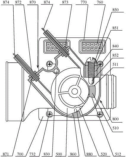
[0035] Such as figure 1 and figure 2 As shown, the throttle body of the present invention includes: a throttle body 100, an air intake passage 200 is arranged inside the throttle body 100; a throttle shaft 300 vertically arranged with the intake passage 200, the throttle shaft 300 passes through a 110 is connected with the throttle body 100; there is a gap in the middle of the throttle shaft 300, and the throttle plate 400 is embedded in it, and two screws 310 fix the throttle plate 400 and the throttle shaft 300 as one; and the return spring 600 acting on the throttle shaft 300, the return spring 600 acts on the throttle shaft 300, so that the throttle shaft 300 is always subjected to the reset force of the rotation to the idle opening.

[0036] An electric control unit 700 is arranged on the side of the throttle body 100. The electric control unit 700 includes an electric control unit housing 710 and a circuit board 720 for engine control. The electric control unit housing...


PUM


Abstract

The invention aims to disclose a throttle body. The throttle body comprises a throttle main body provided with an air inlet channel inside, a throttle shaft perpendicular to the air inlet channel, a throttle piece embedded and fixed on the throttle shaft, a wire pull wheel fixed at one end of the throttle shaft, and a return spring acting on the throttle shaft, wherein an electric control unit is arranged on the side surface of the throttle main body; a permanent magnet is arranged at one end, near the electric control unit, of the throttle shaft, and is concentric with the throttle shaft; and a hall chip for inducing a magnetic field rotating angle of the permanent magnet is welded on a circuit board near the permanent magnet. Compared with the prior art, the throttle body has the characteristics of light and firm structure, no deformation in use, compact structure, good maintainability, good manufacturability, suitability for separate manufacturing of mechanical and electronic parts, good debugging and reliability and long service life, and realizes the purpose.

Description

technical field [0001] The invention relates to a throttle structure, in particular to a throttle body suitable for an electronically controlled injection system of a small gasoline engine. Background technique [0002] The throttle body is used to adjust the intake air volume of the gasoline engine. The throttle body includes a throttle body with an intake passage inside, a throttle shaft perpendicular to the intake passage, a throttle plate embedded and fixed on the throttle shaft, The cable pulley fixed on one end of the throttle shaft and the return spring acting on the throttle shaft. [0003] The existing throttle body has the following problems: [0004] (1) Most of them are made of metal, and the structure is relatively heavy; [0005] (2) The electronic control unit is separated from the throttle body, and the integration is low, which is not conducive to maintenance; [0006] (3) A discrete throttle position sensor is installed on the throttle body, which is lar...

Claims


Application Information

Patent Timeline
IPC IPC(8): F02D9/10
Inventor 汪峰汪洋王斌朱琪
Owner 浙江朗杰电子有限公司
Learn More