Original edition for color display tube shadow mask printing
A color picture tube and shadow mask technology is applied in the field of original plates for color picture tube shadow mask printing, which can solve the problems of neck shrinkage and no transition.
- Summary
- Abstract
- Description
- Claims
- Application Information
AI Technical Summary
Problems solved by technology
Method used
Image

Examples
Embodiment 1
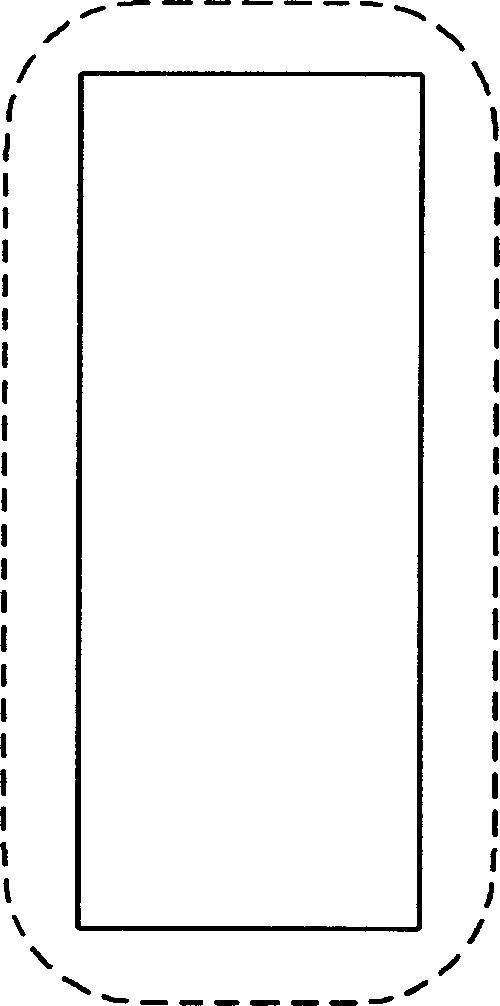
[0039] Such as Figure 8 As shown, the basic hole pattern on the original plate for shadow mask printing is a rectangle with a width (sw) of 220 microns and a length (sl) of 550 microns, and the four corners of the hole shape are designed with the proposed invention. The concave hexagonal compensation pattern, where the height, width, sw_dec, sw_delta, sl_dec1, sl_dec2, tip are 11, 24, 64, 13, 32, 91, 22 microns, the fifth side and the length of the rectangle are 45 degree angle, the shape of the shadow mask hole obtained by etching is as follows Figure 8 As shown by the dotted line in the middle, the width of the shadow mask slot is 320 microns, the length is 650 microns, and the four corners are arcs with a radius of 30 microns, and there is no neck constriction. After such an improved design, the light transmission area can be increased by about 3%, while the length and width of the slots of the shadow mask do not change significantly.
Embodiment 2
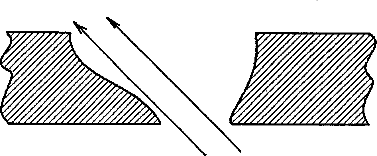
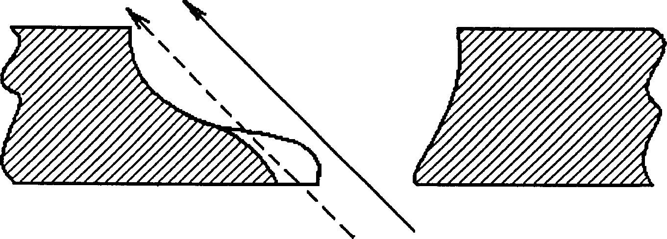
[0041] Both the preceding comparative example and embodiment 1 are cases where the light passes through vertically. When the shadow mask hole is close to the edge of the screen, due to the large deflection angle of the electron beam, the steps of the cone surface will block the electron beam that could have passed through. Such as Figure 2B As shown, the fluorescent powder strips on the fluorescent screen are as image 3 As shown, there is an obvious defect in the corner, which is reflected in the macroscopic view that the brightness of the corner of the color picture tube is obviously insufficient, and the color purity is reduced. In order to change this situation, the slots on the corners of the screen are designed on the side away from the center as Figure 9 The protrusion shown in the lower right corner of the center can make the vermicelli on the fluorescent screen more full, thereby significantly improving the corner brightness of the color picture tube. This kind of...
PUM
| Property | Measurement | Unit |
|---|---|---|
| width | aaaaa | aaaaa |
| length | aaaaa | aaaaa |
| length | aaaaa | aaaaa |
Abstract
Description
Claims
Application Information
 - R&D
- Intellectual Property
- Life Sciences
- Materials
- Tech Scout
- Unparalleled Data Quality
- Higher Quality Content
- 60% Fewer Hallucinations
Browse by: Latest US Patents, China's latest patents, Technical Efficacy Thesaurus, Application Domain, Technology Topic, Popular Technical Reports.
© 2025 PatSnap. All rights reserved.Legal|Privacy policy|Modern Slavery Act Transparency Statement|Sitemap|About US| Contact US: help@patsnap.com