
A cantilever shaft reinforcement device of a cantilever optical fiber take-up machine

A reinforcement device and cantilever shaft technology, which is applied in the field of optical fiber equipment, can solve the problems that the equipment cannot meet the needs of production, the carrying capacity is not large enough, and it is difficult to improve the equipment, etc., to achieve the effect of convenient daily maintenance, improved performance, and beautiful appearance

Active Publication Date: 2018-01-02
FENGHUO COMM SCI & TECH CO LTD
View PDF10 Cites 0 Cited by
  • Summary
  • Abstract
  • Description
  • Claims
  • Application Information

AI Technical Summary

Problems solved by technology

[0003] However, in the actual use process, it is found that the carrying capacity of the existing cantilever fiber optic take-up machine is not large enough, and generally can only carry no more than 500 kilometers of optical fiber, and the maximum winding speed can only be within 2200 m / min. This speed will generate huge vibration and deformation, which greatly restricts production efficiency
With the rapid development of the optical fiber market, the original equipment can no longer meet the needs of production, and optical fiber production requires greater carrying capacity and higher speed take-up equipment
However, the original take-up equipment does not have a lot of room for transformation, and it is difficult to improve the original equipment. If all the existing equipment is eliminated, it will cost a lot of replacement costs. In the case of meager profits in optical fiber production, a large amount of investment will be required. Funds to replace equipment is out of the question

Method used


Image

  • A cantilever shaft reinforcement device of a cantilever optical fiber take-up machine
  • A cantilever shaft reinforcement device of a cantilever optical fiber take-up machine

Examples


Embodiment Construction

[0023] The present invention will be described in further detail below in conjunction with the accompanying drawings and embodiments.

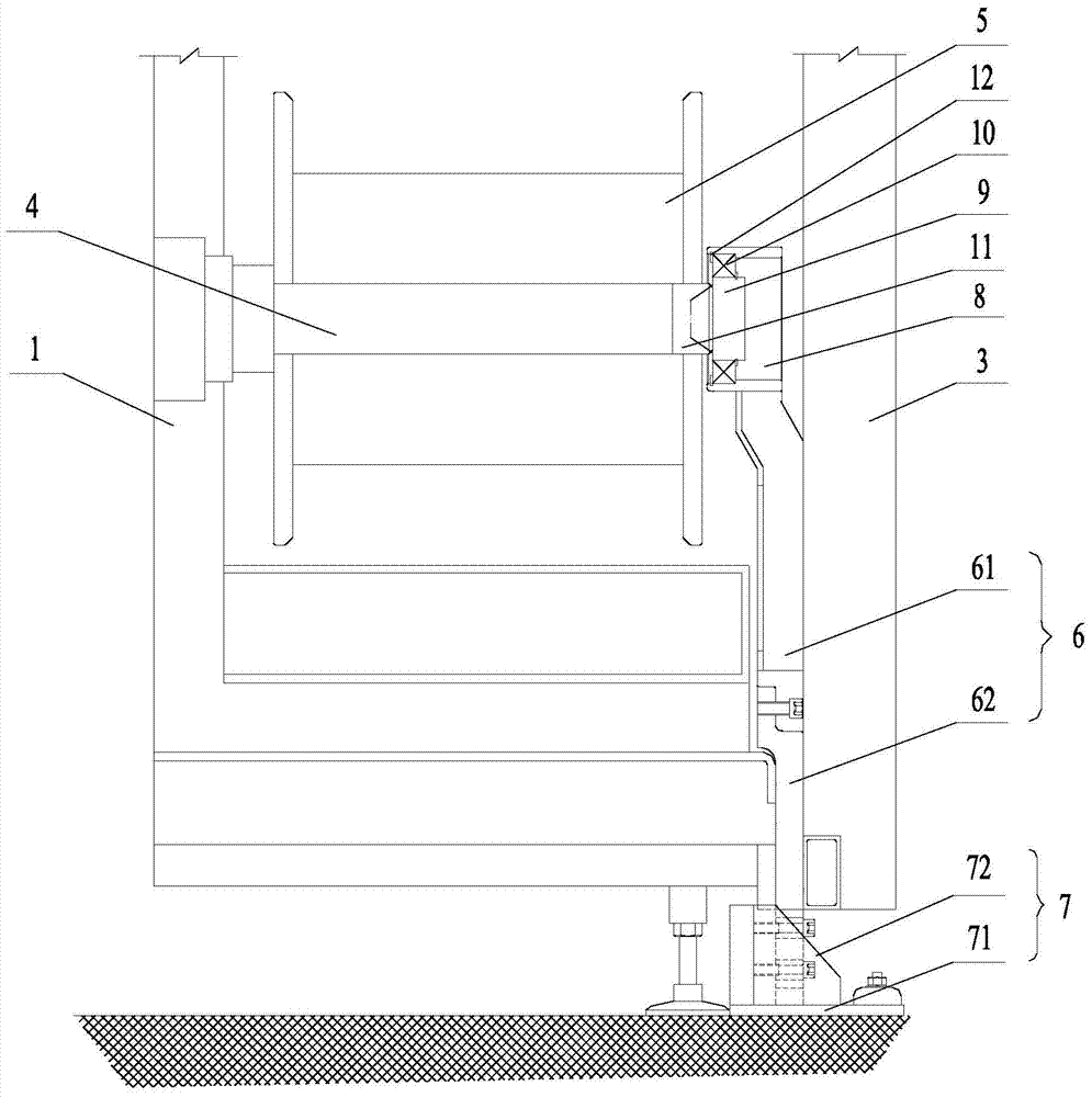
[0024] Such as figure 2 As shown, the present invention provides a cantilever shaft reinforcement device of a cantilever type optical fiber take-up machine, which is installed on the existing cantilever type fiber optic take-up machine, and includes a support member 6 vertically arranged on the inside of the safety door 3. The support member 6 The bottom is connected with a fixing part 7, and the top is provided with a connecting part 8. The supporting part 6 is fixed on the ground through the fixing part 7, and is connected with the suspended end of the cantilever shaft 4 through the connecting part 8.

[0025] Such as figure 2 As shown, the support member 6 includes a bracket 61 and a transition plate 62, the top of the bracket 61 is affixed to the connector 8, the bottom is affixed to the top of the transition plate 62, and the bottom of...


PUM


Abstract

The invention discloses a cantilever shaft reinforcing device of a cantilever type optical fiber take-up machine, and relates to the technical field of optical fiber equipment. The cantilever shaft reinforcing device comprises a supporting part vertically arranged on the inner side of a safety door, and the bottom of the supporting part is connected with a fixing part; the supporting part is fixed to the ground through the fixing part, and a connecting part is arranged on the top of the supporting part; a rotating shaft and a bearing are embedded into the connecting part, and the rotating shaft is connected with a locating sleeve arranged at the free end of a cantilever shaft; the rotating shaft and the locating sleeve are located in a conical surface fit manner, and the outer portion of the rotating shaft is sleeved with the bearing; and the position between the inner ring of the bearing and the rotating shaft and the position between the outer ring of the bearing and the connecting part are each provided with a clamping spring. According to the invention, the bearing capacity and the working efficiency of the take-up machine can be effectively improved without replacement of original cantilever type optical fiber take-up machine equipment, and the cantilever shaft reinforcing device is economical and practical.

Description

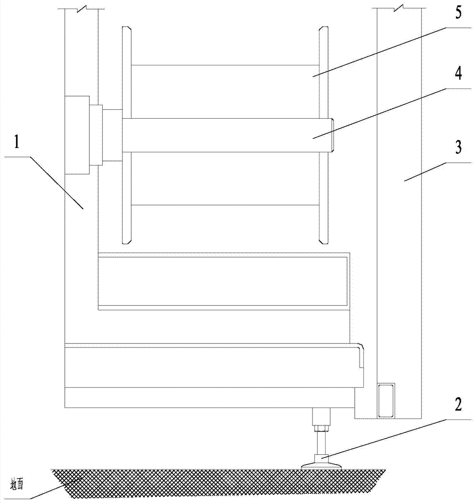
technical field [0001] The invention relates to the technical field of optical fiber equipment, in particular to a cantilever shaft reinforcement device of a cantilever type optical fiber take-up machine. Background technique [0002] At present, most of the take-up equipment in the domestic optical fiber industry adopts a cantilever structure in order to facilitate the upper and lower trays. Such as figure 1 As shown, the cantilever type optical fiber take-up machine mainly includes a body 1, a support frame 2 supporting the body 1, and a safety door 3 arranged on one side of the body 1. A cantilever shaft 4 is horizontally arranged inside the body 1, and one end of the cantilever shaft 4 is fixed. On the inner wall of the body 1, the other end is suspended facing the safety door 3, and the cantilever shaft 4 is sleeved with a winding drum 5 for winding wires. [0003] However, in the actual use process, it is found that the carrying capacity of the existing cantilever fi...

Claims


Application Information

Patent Timeline
Patent Type & Authority Patents(China)
IPC IPC(8): B65H54/72B65H54/547
Inventor 曾革胜刘革胜严勇虎刘志坚余志强李诗愈潘常军
Owner FENGHUO COMM SCI & TECH CO LTD
Learn More